Subaru Crosstrek Service Manual: Removal
LIGHTING SYSTEM > Combination Switch (Light)
REMOVAL
CAUTION:
Before handling the airbag system components, refer to “CAUTION” of “General Description” in “AIRBAG SYSTEM”. General Description > CAUTION">
1. Set the tire to the straight-ahead position.
2. Disconnect the ground cable from battery and wait for at least 60 seconds before starting work. NOTE">
3. Remove the driver’s airbag module. Driver’s Airbag Module > REMOVAL">
4. Remove the steering wheel. Steering Wheel > REMOVAL">
5. Remove the cover assembly - column.
(1) Release the screws and claws.
(2) Remove the cap - key cylinder (a).
(3) Release the claw, and remove the cover assembly - column UPR and the cover assembly - column LWR.
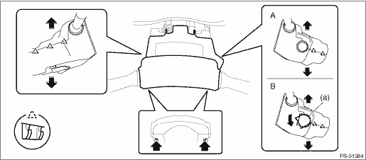
A | Model without keyless access with push button start | B | Model with keyless access with push button start |
6. Remove the steering roll connector. Roll Connector > REMOVAL">
7. Remove the switch assembly - combination wiper select. Combination Switch (Wiper) > REMOVAL">
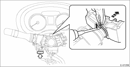
8. Remove the switch assembly - combination turn dimmer.
(1) Disconnect the connector, and loosen the clamp to release the claws.
(2) Pull out the switch assembly - combination turn dimmer from the column assembly - steering.
 Inspection
LIGHTING SYSTEM > Combination Switch (Light)INSPECTIONMeasure the resistance between connector terminals. If it is not within the standard value, replace the switch assembly - combination turn dimm ...
 Installation
LIGHTING SYSTEM > Combination Switch (Light)INSTALLATIONCAUTION:• Before handling the airbag system components, refer to “CAUTION” of “General Description” in “A ...
Other materials:
Storage compartment
CAUTION
Always keep all storage compartments in the Subaru Ascent closed while
driving to reduce the risk of injury during sudden braking or collisions.
Do not store flammable, pressurized, or corrosive materials such as aerosol
cans or chemical containers in any storage compartment.
...
Adjustment
SECURITY AND LOCKS > Impact SensorADJUSTMENT1. CHECK IMPACT SENSOR1. Pull out the key from the ignition switch, or turn the ignition switch to OFF.2. Close all the windows.3. Close all the doors and rear gate. Leave open the front hood.4. Press the LOCK button of the keyless transmitter or access ...
Assembly
CLUTCH SYSTEM > Master CylinderASSEMBLY1. Apply a coat of grease to the contact surfaces of the push rod and piston before installation.Grease:SILICONE GREASE G-40M or equivalent2. Assemble in the reverse order of disassembly.Tightening torque:10 N·m (1.0 kgf-m, 7.4 ft-lb) ...
