Subaru Crosstrek Service Manual: Removal
GLASS/WINDOWS/MIRRORS > Power Window Control Switch
REMOVAL
1. MAIN SWITCH
1. Disconnect the ground cable from battery and wait for at least 60 seconds before starting work. NOTE">
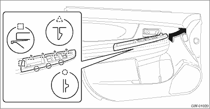
2. Remove the trim panel - front door. Door Trim > REMOVAL">
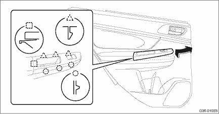
3. Remove the panel - power window main switch.
CAUTION:
Be careful not to damage the trim panel - front door with the panel - power window main switch.
(1) Insert a sheet of protective paper (a) between panel - power window main switch and trim panel - front door.
(2) Remove the screws and disconnect the connector.
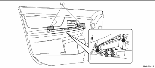
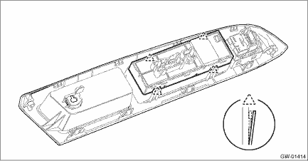
(3) Release the claws, and then remove the panel - power window main switch.
(4) Release the claws, and then remove the switch - power window main.
2. SUB-SWITCH
Switch - power window sub front
For removal of the switch - power window sub front on the passenger’s seat, refer to the removal procedure of the switch - power window main. Power Window Control Switch > REMOVAL">
Switch - power window sub rear
1. Disconnect the ground cable from battery and wait for at least 60 seconds before starting work. NOTE">
2. Remove the trim panel - rear door. Door Trim > REMOVAL">
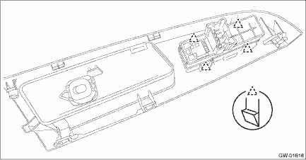
3. Remove the panel - power window sub switch rear.
CAUTION:
Be careful not to damage the trim panel - rear door with the panel - power window sub switch rear.
(1) Insert a sheet of protective paper (a) between panel - power window sub switch rear and trim panel - rear door.
(2) Remove the screws and disconnect the connector.
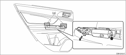
(3) Release the claws, and then remove the panel - power window sub switch rear.
4. Release the claws, and then remove the switch - power window sub rear.
 Inspection
GLASS/WINDOWS/MIRRORS > Power Window Control SwitchINSPECTION1. MAIN SWITCH• Driver’s seatCAUTION:Since the switch - power window main is controlled by CPU, do not check continuity for ...
 Installation
GLASS/WINDOWS/MIRRORS > Power Window Control SwitchINSTALLATIONCAUTION:• After installing the switch - power window main, always perform the initial setting.Failure to do so may cause the imp ...
Other materials:
Electronic Brake Force Distribution (EBD) system
The EBD system maximizes the effectiveness
of the brakes by allowing the rear
brakes to supply a greater proportion of
the braking force. It functions by adjusting
the distribution of braking force to the rear
wheels in accordance with the vehicle's
loading condition and speed.
The EBD syst ...
Clutch system Inspection and adjustment
PERIODIC MAINTENANCE SERVICES > Clutch SystemINSPECTION AND ADJUSTMENTRefer to “CL” section for inspection and adjustment of clutch system. Clutch Pedal > INSPECTION"> Clutch Pedal > ADJUSTMENT"> ...
Removal
GLASS/WINDOWS/MIRRORS > Rear Door GlassREMOVAL1. Disconnect the ground cable from battery. NOTE">2. Remove the trim panel - rear door. Door Trim > REMOVAL">3. Remove the sealing cover - rear door. Rear Sealing Cover > REMOVAL">4. Attach the battery ground cable an ...
