Subaru Crosstrek Service Manual: Inspection
GLASS/WINDOWS/MIRRORS > Power Window Control Switch
INSPECTION
1. MAIN SWITCH
• Driver’s seat
CAUTION:
Since the switch - power window main is controlled by CPU, do not check continuity for switch alone with the circuit tester. Performing continuity check with circuit tester can damage the switch - power window main circuit.
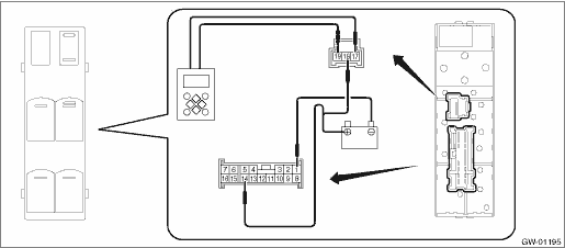
Check output from the switch - power window main to the driver’s side motor using the oscilloscope function in the Subaru Select Monitor.
1. Remove the switch - power window main.
2. Connect the battery and the Subaru Select Monitor to the switch - power window main terminal.
CAUTION:
Never mix up the terminals when connecting the harness connector of the switch - power window main and the battery. If the connection is wrong, the switch - power window main may be damaged.
NOTE:
• When the battery is connected to the switch - power window main terminal, the letters “AUTO” on the driver’s side knob illuminates.
• For detailed procedures, refer to “Subaru Select Monitor Operation Manual”.
3. Operate the switch - power window main and check the output.
NOTE:
Since output time during window UP operation is extremely short, it cannot be checked without using a measuring instrument such as oscilloscope. Output is constantly produced while the switch is operated for window DOWN operation.
Inspection conditions | Output time | Standard |
AUTO UP | Approx. 130 ms | Battery voltage |
UP | ||
OFF | — | 0 V |
DOWN | During switch operation | Battery voltage |
AUTO DOWN | Approx. 300 ms |
4. If the inspection result is not within the standard, replace the switch - power window main.
• Except for driver’s seat
1. Check the resistance between terminals of the switch - power window main.
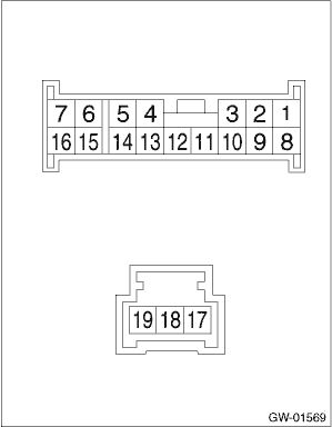
Terminal No. | Inspection conditions | Standard | |
Passenger’s seat | 14 — 8 1 — 2 | UP | Less than 1 ? |
14 — 2 14 — 8 | OFF | 1 M? or more | |
1 — 8 1 — 2 8 — 2 | Less than 1 ? | ||
14 — 2 1 — 8 | DOWN | Less than 1 ? | |
Rear LH | 14 — 15 1 — 16 | UP | Less than 1 ? |
14 — 15 14 — 16 | OFF | 1 M? or more | |
1 — 15 1 — 16 15 — 16 | Less than 1 ? | ||
14 — 16 1 — 15 | DOWN | Less than 1 ? | |
Rear RH | 14 — 7 1 — 6 | UP | Less than 1 ? |
14 — 7 14 — 6 | OFF | 1 M? or more | |
1 — 6 1 — 7 6 — 7 | Less than 1 ? | ||
14 — 6 1 — 7 | DOWN | Less than 1 ? |
2. If the inspection result is not within the standard, replace the switch - power window main.
2. SUB-SWITCH
1. Remove the switch - power window sub.
2. Check the resistance between terminals of the switch - power window sub.
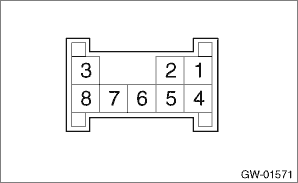
Terminal No. | Inspection conditions | Standard | |
Passenger seat, rear | 6 — 5 8 — 7 | UP | Less than 1 ? |
7 — 6 4 — 6 | OFF | 1 M? or more | |
5 — 4 8 — 7 | Less than 1 ? | ||
6 — 8 5 — 4 | DOWN | Less than 1 ? |
3. If the inspection result is not within the standard, replace the switch - power window sub.

 Removal
GLASS/WINDOWS/MIRRORS > Power Window Control SwitchREMOVAL1. MAIN SWITCH1. Disconnect the ground cable from battery and wait for at least 60 seconds before starting work. NOTE">2. Remove t ...
Other materials:
Inspection
FUEL INJECTION (FUEL SYSTEMS)(H4DO) > Tumble Generator Valve AssemblyINSPECTION1. CHECK MOTOR1. Connect the battery positive terminal to terminal No. 5 and the battery ground terminal to terminal No. 4, and check that the valve is fully opened on LH side and the valve is fully closed on RH side.C ...
Adjustment
MANUAL TRANSMISSION AND DIFFERENTIAL(5MT) > Front Differential AssemblyADJUSTMENT1. DIFFERENTIAL BEVEL PINION GEAR BACKLASH1. Disassemble the front differential assembly. Front Differential Assembly > DISASSEMBLY">2. Select the adjusting washer from the table and install.Adjusting was ...
Dtc u0140 lost communication with body control module
TELEMATICS SYSTEM (DIAGNOSTICS) > Diagnostic Procedure with Diagnostic Trouble Code (DTC)DTC U0140 LOST COMMUNICATION WITH BODY CONTROL MODULEDetected when CAN data is not received from body integrated unit.NOTE:Perform the diagnosis for LAN system. Basic Diagnostic Procedure > PROCEDURE" ...
