Subaru Crosstrek Service Manual: Assembly
FRONT SUSPENSION > Front Arm
ASSEMBLY
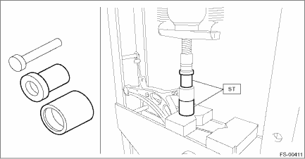
1. BUSHING FRONT - FRONT ARM
1. Before assembly, inspect the following items and replace any faulty part with a new one.
• Check the front arm assembly for damage or cracks, and replace if defective.
• Visually check the bushing for abnormal cracks, fatigue or damage.
• Visually check the dust cover on the ball joint assembly for damage.
2. Align the alignment mark on the front arm assembly to the split portion of the bushing intermediate plate of the busing front - front arm.
3. Using the ST and a press, assemble the busing front - front arm.
PREPARATION TOOL:
ST: INSTALLER & REMOVER SET (927680000)
2. BUSHING REAR - FRONT ARM
1. Before installation, inspect the following items and replace any faulty part with a new one.
• Check the front arm assembly for damage or cracks, and replace if defective.
• Visually check the bushing for abnormal cracks, fatigue or damage.
• Visually check the dust cover on the ball joint assembly for damage.
2. Align a line extending from the center of recess portion with the ball joint after placing the protrusion (A) of recess portion to the ball joint side of the front arm assembly.
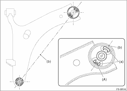
(a) | Recess section | (b) | Center line of recess section |
3. Using the ST and a press, install the busing rear - front arm.
CAUTION:
Align the upper face of front arm assembly and the end of bushing during installation.
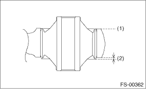
(1) | Aligned |
(2) | Not aligned |
PREPARATION TOOL:
ST1: REMOVER (20299AG000)
ST2: BASE (20299AG010)
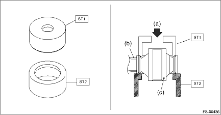
(a) | Press | (b) | Front arm ASSY | (c) | Bushing rear - front arm |
 Front arm
...
 Removal
FRONT SUSPENSION > Front ArmREMOVAL1. Lift up the vehicle, and then remove the front wheels.2. Remove the under cover - front. Front Under Cover > REMOVAL">3. Remove the front arm assem ...
Other materials:
General precautions regarding SRS airbag system
The Subaru Ascent is equipped with a sophisticated Supplemental Restraint System
(SRS) designed to enhance occupant protection during collisions. However, for the
system to perform effectively, it must always be used in conjunction with properly
fastened seatbelts. The SRS airbag system in the ...
Installation
EMISSION CONTROL (AUX. EMISSION CONTROL DEVICES)(H4DO) > EGR Control ValveINSTALLATIONInstall in the reverse order of removal.NOTE:Use new O-rings and gaskets.Tightening torque:22 N·m (2.2 kgf-m, 16.2 ft-lb)Tightening torque:3 N·m (0.3 kgf-m, 2.2 ft-lb) ...
Removal
STARTING/CHARGING SYSTEMS(H4DO) > BatteryREMOVAL1. Disconnect the positive (+) terminal after disconnecting the negative (−) terminal of battery.2. Remove the battery cable holder from the battery rod.3. Remove the flange nut from battery rod and remove battery holder.4. Remove the battery. ...
