Subaru Crosstrek Service Manual: Installation
FUEL INJECTION (FUEL SYSTEMS)(H4DO) > Intake Manifold
INSTALLATION
1. Install the engine wiring harness. Engine Wiring Harness > INSTALLATION">
2. Install the intake manifold to the tumble generator valve assembly.
NOTE:
Use a new gasket.
Tightening torque:
8.3 N·m (0.8 kgf-m, 6.1 ft-lb)
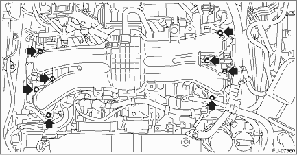
3. Connect the fuel delivery tube and evaporation hose.
(1) Connect the evaporation hose to fuel pipe assembly.
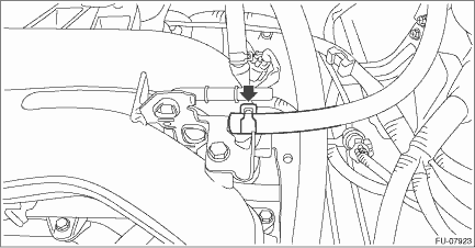
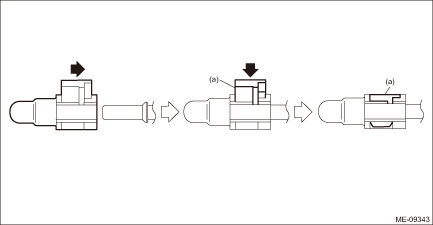
(2) Connect the quick connector of the fuel delivery tube to the fuel pipe assembly, and secure the fuel delivery tube using clip (A).
CAUTION:
• Check that there is no damage or dust on the quick connector. If necessary, clean the seal surface of the pipe.
• When connecting the quick connector, make sure to insert it all the way in before locking the slider.
• When it is difficult to lock the slider, check that the connector is fully inserted.
• After locking the slider, check again that the quick connector is securely connected.
NOTE:
Connect the quick connector as shown in the figure.
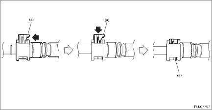
(a) | Slider |
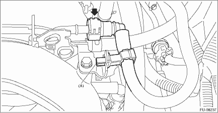
4. Connect the fuel delivery pipe to the fuel pipe LH.
CAUTION:
• Check that there is no damage or dust on the quick connector. If necessary, clean the seal surface of the pipe.
• When connecting the quick connector, make sure to insert it all the way in before locking the slider.
• When it is difficult to lock the slider, check that the connector is fully inserted.
• After locking the slider, check again that the quick connector is securely connected.
NOTE:
Connect the quick connector as shown in the figure.
(a) | Slider |
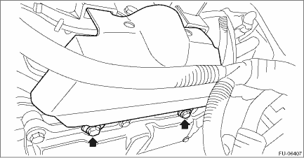
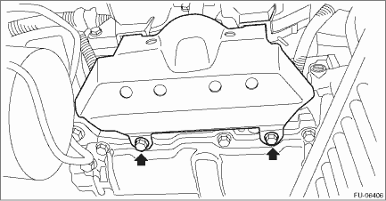
5. Install the intake manifold protector LH.
Tightening torque:
6.4 N·m (0.7 kgf-m, 4.7 ft-lb)
6. Connect the fuel delivery pipe to the fuel pipe RH.
CAUTION:
• Check that there is no damage or dust on the quick connector. If necessary, clean the seal surface of the pipe.
• When connecting the quick connector, make sure to insert it all the way in before locking the slider.
• When it is difficult to lock the slider, check that the connector is fully inserted.
• After locking the slider, check again that the quick connector is securely connected.
NOTE:
Connect the quick connector as shown in the figure.
(a) | Slider |
7. Install the intake manifold protector RH.
Tightening torque:
6.4 N·m (0.7 kgf-m, 4.7 ft-lb)
8. Install the air cleaner case (rear) together with the air cleaner element. Air Cleaner Case > INSTALLATION">
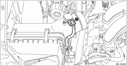
9. Secure the bulkhead wiring harness with clip (A) and connect the connector to the mass air flow and intake air temperature sensor.
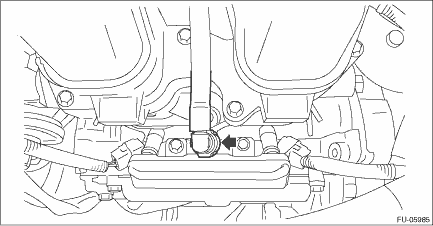
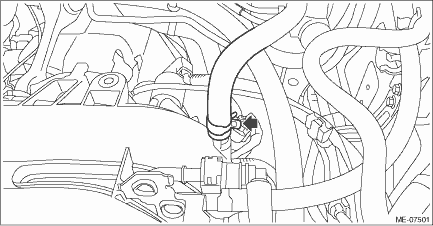
10. Connect the brake booster vacuum hose to the intake manifold.
11. Connect the PCV hose (A) to intake manifold.
12. Connect the connector (B) to the manifold absolute pressure sensor.
13. Connect the connector (C) to the throttle position sensor.
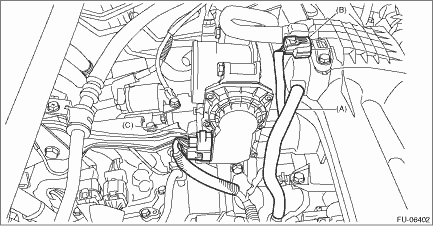
14. Connect the connector (A) to the purge control solenoid valve.
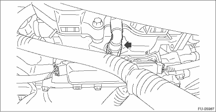
15. Tighten the nut (C) and bolt (B) which hold EGR pipe to the water pipe assembly.
NOTE:
• Use a new gasket.
• Always tighten the EGR pipe at (C) first, and then (B).
Tightening torque:
6.4 N·m (0.7 kgf-m, 4.7 ft-lb)

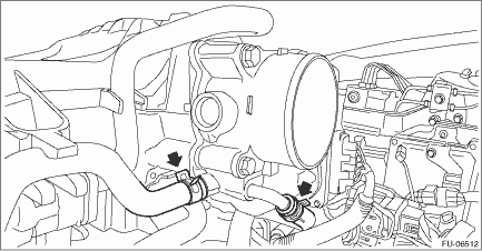
16. Install the preheater hose to the throttle body.
17. Install the air intake boot. Air Intake Boot > INSTALLATION">
18. Lift up the vehicle.
19. Install the under cover. Front Under Cover > INSTALLATION">
20. Lower the vehicle.
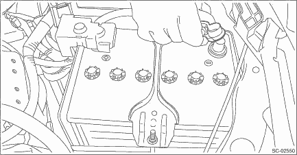
21. Connect the battery ground terminal.
22. Fill engine coolant. Engine Coolant > REPLACEMENT">
 Inspection
FUEL INJECTION (FUEL SYSTEMS)(H4DO) > Intake ManifoldINSPECTION1. Check that the intake manifold and fuel pipe have no deformation, cracks and other damages.2. Check that the hose has no cracks, da ...
 Knock sensor
...
Other materials:
Disassembly
REAR SUSPENSION > Rear Trailing LinkDISASSEMBLY1. BUSHING A - TRAILING LINKUsing the ST, push out the bushing A - trailing link.Preparation tool:ST-A: INSTALLER (899874100)ST-B: INSTALLER & REMOVER (BASE) (20099PA010)2. BUSHING - TRAILING LINKFor the removal procedure of bushing - trailing li ...
Dtc p0122 throttle/pedal position sensor/switch "a" circuit low
ENGINE (DIAGNOSTICS)(H4DO) > Diagnostic Procedure with Diagnostic Trouble Code (DTC)DTC P0122 THROTTLE/PEDAL POSITION SENSOR/SWITCH "A" CIRCUIT LOWDTC detecting condition:Immediately at fault recognitionTrouble symptom:• Improper idling• Engine stall• Poor driving perf ...
Removal
CONTINUOUSLY VARIABLE TRANSMISSION(TR580) > Primary Pulley and Secondary PulleyREMOVALNOTE:Always replace primary pulley and secondary pulley as an assembly because they are non-disassembled parts.1. Remove the transmission assembly from the vehicle. Automatic Transmission Assembly > REMOVAL& ...
