Subaru Crosstrek Service Manual: Dtc b2300 rear radar circuit low
Blind Spot Detection/Rear Cross Traffic Alert (DIAGNOSTICS) > Diagnostic Procedure with Diagnostic Trouble Code (DTC)
DTC B2300 REAR RADAR CIRCUIT LOW
DTC detecting condition:
• Short circuit to ground in the harness between radar sensor and outer mirror assembly
• Ground short circuit of the harness in outer mirror assembly module (Malfunction of the outer mirror assembly)
• Defective radar sensor
Trouble symptom:
• All functions of BSD/RCTA stop.
• Fail icon is displayed in the combination meter LCD display.
• Failure-related notification is displayed for approx. two seconds on LCD display in the combination meter.
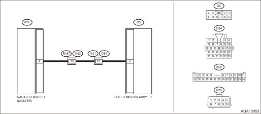
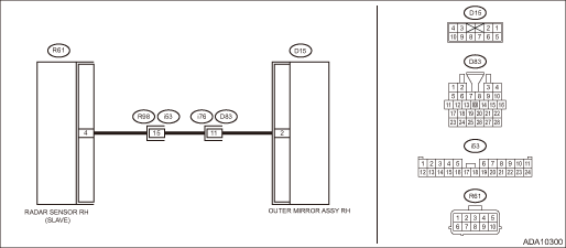
Wiring diagram:
NOTE:
For the coupling connector, refer to “WIRING SYSTEM”.
BSD/RCTA system Blind Spot Detection/Rear Cross Traffic Alert > WIRING DIAGRAM">
• Radar sensor LH
• Radar sensor RH
NOTE:
Check and replace the side that displayed the DTC.
| STEP | CHECK | YES | NO |
1.CHECK DTC.
Read the DTC. Read Diagnostic Trouble Code (DTC) > OPERATION">
Is DTC B2327 displayed? (Current malfunction)
Perform the diagnosis according to DTC. Diagnostic Procedure with Diagnostic Trouble Code (DTC) > DTC B2327 REAR RADAR INTERNAL FAILURE (INTERNAL ELECTRIC CIRCUIT)">
Diagnostic Procedure with Diagnostic Trouble Code (DTC) > DTC B2300 REAR RADAR CIRCUIT LOW">Go to Step 2.
2.CHECK DTC.
Read the DTC. Read Diagnostic Trouble Code (DTC) > OPERATION">
Is DTC B2300 displayed? (Current malfunction)
Diagnostic Procedure with Diagnostic Trouble Code (DTC) > DTC B2300 REAR RADAR CIRCUIT LOW">Go to Step 3.
Even if DTC is displayed, the circuit has returned to a normal condition at this time. Reproduce the failure, and then perform the diagnosis again.
NOTE:
In this case, temporary poor contact of connector, temporary open or short circuit of harness may be the cause.
3.CHECK OPERATION CHECK MODE.
Perform the system operation check mode «Door mirror indicator active test» from «Subaru Rear Vehicle Detection(RH)» or «Subaru Rear Vehicle Detection(LH)». System Operation Check Mode">
Does the indicator illuminate?
Even if DTC is displayed, the circuit has returned to a normal condition at this time. Reproduce the failure, and then perform the diagnosis again.
NOTE:
In this case, temporary poor contact of connector, temporary open or short circuit of harness may be the cause.
Diagnostic Procedure with Diagnostic Trouble Code (DTC) > DTC B2300 REAR RADAR CIRCUIT LOW">Go to Step 4.
4.CHECK HARNESS (GROUND SHORT CIRCUIT).
1) Disconnect the radar sensor connector.
2) Disconnect the outer mirror assembly connector.
3) Using a tester, measure the resistance between radar sensor connector (harness side) and the chassis ground.
Connector & terminal
Radar sensor LH
(R25) No. 4 — Chassis ground:
Radar sensor RH
(R61) No. 4 — Chassis ground:
Is the resistance 1 M? or more?
Diagnostic Procedure with Diagnostic Trouble Code (DTC) > DTC B2300 REAR RADAR CIRCUIT LOW">Go to Step 5.
Repair the short to ground in harness between radar sensor connector and outer mirror assembly connector.
5.CHECK CONNECTOR.
Check the radar sensor connector and the outer mirror assembly connector.
Is there any fault? (Insecure connection, poor contact, etc.)
Repair the connector.
Diagnostic Procedure with Diagnostic Trouble Code (DTC) > DTC B2300 REAR RADAR CIRCUIT LOW">Go to Step 6.
6.CHECK OUTER MIRROR ASSEMBLY.
Perform unit-check for the outer mirror assembly. Outer Mirror Assembly">
Is there any fault?
Replace the outer mirror assembly. Outer Mirror Assembly">
Diagnostic Procedure with Diagnostic Trouble Code (DTC) > DTC B2300 REAR RADAR CIRCUIT LOW">Go to Step 7.
7.CHECK BSD/RCTA.
1) Restore the vehicle to its original state.
2) Perform the Inspection Mode. Inspection Mode">
Is DTC B2300 displayed? (Current malfunction)
Replace the radar sensor. Radar Sensor">
Even if DTC is displayed, the circuit has returned to a normal condition at this time. Reproduce the failure, and then perform the diagnosis again.
NOTE:
In this case, temporary poor contact of connector, temporary open or short circuit of harness may be the cause.
 Dtc u0140 lost communication with body control module
Blind Spot Detection/Rear Cross Traffic Alert (DIAGNOSTICS) > Diagnostic Procedure with Diagnostic Trouble Code (DTC)DTC U0140 LOST COMMUNICATION WITH BODY CONTROL MODULEDetected when CAN data from ...
 Dtc b2301 rear radar circuit high
Blind Spot Detection/Rear Cross Traffic Alert (DIAGNOSTICS) > Diagnostic Procedure with Diagnostic Trouble Code (DTC)DTC B2301 REAR RADAR CIRCUIT HIGHDTC detecting condition:• Open circuit or ...
Other materials:
Front passenger's seatbelt
The front passenger's seatbelt has
shoulder belt and lap belt pretensioner.
Seatbelt retractor assembly (shoulder
belt pretensioner)
Lap belt pretensioner
On the front passenger's side, the
shoulder belt pretensioner is supplemented
by a lap belt pretensioner, which is
located at ...
Dtc p0453 evap system (cpc) pressure sensor/switch circuit high
ENGINE (DIAGNOSTICS)(H4DO) > Diagnostic Procedure with Diagnostic Trouble Code (DTC)DTC P0453 EVAP SYSTEM (CPC) PRESSURE SENSOR/SWITCH CIRCUIT HIGHDTC detecting condition:Immediately at fault recognitionCAUTION:After servicing or replacing faulty parts, perform Clear Memory Mode Clear Memory Mod ...
Component
EyeSight > General DescriptionCOMPONENT1. STEREO CAMERA(1)Shim (washer)(4)Stereo camera cover ASSYTightening torque: N·m (kgf-m, ft-lb)(2)Camera plate(5)CapT:5.5±1.0 (0.56±0.10, 4.1±0.7)(3)Stereo camera ...
