Subaru Crosstrek Service Manual: Dtc b2301 rear radar circuit high
Blind Spot Detection/Rear Cross Traffic Alert (DIAGNOSTICS) > Diagnostic Procedure with Diagnostic Trouble Code (DTC)
DTC B2301 REAR RADAR CIRCUIT HIGH
DTC detecting condition:
• Open circuit or short circuit to power supply in harness between radar sensor and outer mirror assembly.
• Open circuit or short circuit to power supply of harness in the outer mirror assembly module. (Malfunction of the outer mirror assembly)
• Open circuit or short circuit to power supply of harness between outer mirror assembly and ground.
• Defective radar sensor
Trouble symptom:
• All functions of BSD/RCTA stop.
• Fail icon is displayed in the combination meter LCD display.
• Failure-related notification is displayed for approx. two seconds on LCD display in the combination meter.
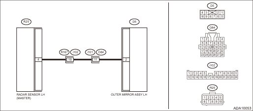
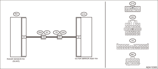
Wiring diagram:
NOTE:
For the coupling connector, refer to “WIRING SYSTEM”.
BSD/RCTA system Blind Spot Detection/Rear Cross Traffic Alert > WIRING DIAGRAM">
• Radar sensor LH
• Radar sensor RH
NOTE:
Check and replace the side that displayed the DTC.
| STEP | CHECK | YES | NO |
1.CHECK DTC.
Read the DTC. Read Diagnostic Trouble Code (DTC) > OPERATION">
Is DTC B2327 displayed? (Current malfunction)
Perform the diagnosis according to DTC. Diagnostic Procedure with Diagnostic Trouble Code (DTC) > DTC B2327 REAR RADAR INTERNAL FAILURE (INTERNAL ELECTRIC CIRCUIT)">
Diagnostic Procedure with Diagnostic Trouble Code (DTC) > DTC B2301 REAR RADAR CIRCUIT HIGH">Go to Step 2.
2.CHECK DTC.
Read the DTC. Read Diagnostic Trouble Code (DTC) > OPERATION">
Is DTC B2301 displayed? (Current malfunction)
Diagnostic Procedure with Diagnostic Trouble Code (DTC) > DTC B2301 REAR RADAR CIRCUIT HIGH">Go to Step 3.
Even if DTC is displayed, the circuit has returned to a normal condition at this time. Reproduce the failure, and then perform the diagnosis again.
NOTE:
In this case, temporary poor contact of connector, temporary open or short circuit of harness may be the cause.
3.CHECK OPERATION CHECK MODE.
Perform the system operation check mode «Door mirror indicator active test» from «Subaru Rear Vehicle Detection(RH)» or «Subaru Rear Vehicle Detection(LH)». System Operation Check Mode">
Does the indicator illuminate?
Even if DTC is displayed, the circuit has returned to a normal condition at this time. Reproduce the failure, and then perform the diagnosis again.
NOTE:
In this case, temporary poor contact of connector, temporary open or short circuit of harness may be the cause.
Diagnostic Procedure with Diagnostic Trouble Code (DTC) > DTC B2301 REAR RADAR CIRCUIT HIGH">Go to Step 4.
4.CHECK HARNESS (OPEN CIRCUIT).
1) Disconnect the radar sensor connector.
2) Disconnect the outer mirror assembly connector.
3) Using a tester, measure the resistance between radar sensor connector (harness side) and outer mirror assembly connector (harness side).
Connector & terminal
Radar sensor LH
(R25) No. 4 — (D5) No. 2:
Radar sensor RH
(R61) No. 4 — (D15) No. 2:
Is the resistance less than 1 ??
Diagnostic Procedure with Diagnostic Trouble Code (DTC) > DTC B2301 REAR RADAR CIRCUIT HIGH">Go to Step 5.
Repair the open circuit of harness between radar sensor connector and outer mirror assembly connector.
5.CHECK HARNESS (SHORT CIRCUIT TO POWER SUPPLY).
1) Turn the ignition switch to ON.
2) Using a tester, measure the voltage between radar sensor connector (harness side) and the chassis ground.
Connector & terminal
Radar sensor LH
(R25) No. 4 (+) — Chassis ground (−):
Radar sensor RH
(R61) No. 4 (+) — Chassis ground (−):
Is the voltage less than 1 V?
Diagnostic Procedure with Diagnostic Trouble Code (DTC) > DTC B2301 REAR RADAR CIRCUIT HIGH">Go to Step 6.
Repair the short circuit to power supply in harness between radar sensor connector and outer mirror assembly connector.
6.CHECK CONNECTOR.
Check the radar sensor connector and the outer mirror assembly connector.
Is there any fault? (Insecure connection, poor contact, etc.)
Repair the connector.
Diagnostic Procedure with Diagnostic Trouble Code (DTC) > DTC B2301 REAR RADAR CIRCUIT HIGH">Go to Step 7.
7.CHECK OUTER MIRROR ASSEMBLY.
Perform unit-check for the outer mirror assembly. Outer Mirror Assembly">
Is there any fault?
Replace the outer mirror assembly. Outer Mirror Assembly">
Diagnostic Procedure with Diagnostic Trouble Code (DTC) > DTC B2301 REAR RADAR CIRCUIT HIGH">Go to Step 8.
8.CHECK BSD/RCTA.
1) Restore the vehicle to its original state.
2) Perform the Inspection Mode. Inspection Mode">
Is DTC B2301 displayed? (Current malfunction)
Replace the radar sensor. Radar Sensor">
Even if DTC is displayed, the circuit has returned to a normal condition at this time. Reproduce the failure, and then perform the diagnosis again.
NOTE:
In this case, temporary poor contact of connector, temporary open or short circuit of harness may be the cause.
 Dtc b2300 rear radar circuit low
Blind Spot Detection/Rear Cross Traffic Alert (DIAGNOSTICS) > Diagnostic Procedure with Diagnostic Trouble Code (DTC)DTC B2300 REAR RADAR CIRCUIT LOWDTC detecting condition:• Short circuit to ...
 Dtc b2304 rear radar on-off switch stuck
Blind Spot Detection/Rear Cross Traffic Alert (DIAGNOSTICS) > Diagnostic Procedure with Diagnostic Trouble Code (DTC)DTC B2304 REAR RADAR ON-OFF SWITCH STUCKDTC detecting condition:• BSD/RCTA ...
Other materials:
Subaru select monitor Operation
CRUISE CONTROL SYSTEM (DIAGNOSTICS) > Subaru Select MonitorOPERATION1. GENERAL DESCRIPTIONThe on-board diagnosis function of the cruise control system uses Subaru Select Monitor.The on-board diagnosis function operates in two categories, which are used depending on the type of problems;1. Cruise ...
Inspection
EMISSION CONTROL (AUX. EMISSION CONTROL DEVICES)(H4DO) > EGR Control ValveINSPECTION1. Check that the EGR control valve has no deformation, cracks or other damages.2. Measure the resistance between EGR control valve terminals.Terminal No.Standard2 and 122±2 ?2 and 322±2 ?5 and 422±2 ?5 and 622 ...
Installation
DRIVE SHAFT SYSTEM > Propeller ShaftINSTALLATION1. Before installation, check the following items, and replace the propeller shaft assembly as necessary.• Dents or cracks on the tube surface• Splines for deformation or abnormal wear• Unsmooth joint operation or abnormal noise&bu ...
