Subaru Crosstrek Service Manual: Removal
EXTERIOR/INTERIOR TRIM > Lower Inner Trim
REMOVAL
CAUTION:
• Before handling the airbag system components, refer to “CAUTION” of “General Description” in “AIRBAG SYSTEM”. General Description > CAUTION">
• Airbag system satellite safing sensor is located in the lower of the rear seat cushion center. Be careful not to apply strong impact to the sensor when performing operations, while the rear seat cushion is removed.
1. Release the claws, and then remove the cover side sill - front INN.
CAUTION:
Do not pull with excessive force. Doing so may damage the claws of the cover side sill - front INN.
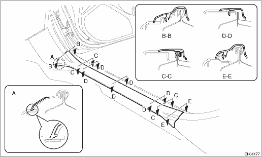
2. Remove the clips, and remove the cover side sill - front.
3. Remove the rear seat cushion assembly. Rear Seat > REMOVAL">
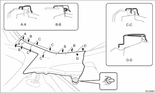
4. Release the clips and claws, and then remove the cover side sill - rear INN.
CAUTION:
Do not pull with excessive force. Doing so may damage the claws of the cover side sill - rear INN.
5. Remove the trim panel - center pillar LWR.
(1) Release the clip by pulling the trim panel - center pillar LWR toward you.
(2) Expand the claws of the trim panel - center pillar LWR outward, and remove it from the trim panel - center pillar UPR.
CAUTION:
Do not expand the trim panel - center pillar LWR excessively. Doing so may damage the trim.
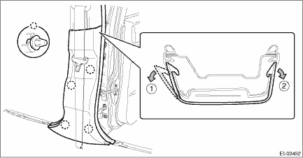
NOTE:
First release the claw located to the front of the vehicle.
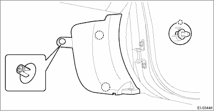
6. Disconnect the claws and remove the cover - catcher.
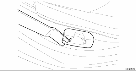
NOTE:
Remove the cover - catcher by using a plastic remover.
 Installation
EXTERIOR/INTERIOR TRIM > Lower Inner TrimINSTALLATIONInstall each part in the reverse order of removal.NOTE:Assemble the trim panel - center pillar LWR to the trim panel - center pillar UPR securel ...
 Mud guard
...
Other materials:
Component
GLASS/WINDOWS/MIRRORS > General DescriptionCOMPONENT1. FRONT DOOR GLASS(1)Running channel - front door(5)Regulator & motor ASSY - frontTightening torque: N·m (kgf-m, ft-lb)(2)Glass ASSY - front door(6)Sash COMPL - partitionT1:2.2 (0.22, 1.6)(3)Weather strip outer - front door(7)Weather ...
Precautions against vehicle modification
WARNING
To avoid accidental activation of the
system or rendering the system
inoperative, which may result in
serious injury, no modifications
should be made to any components
or wiring of the SRS airbag system.
This includes following modifications.
Installation of custom steering
wh ...
Installation
FUEL INJECTION (FUEL SYSTEMS)(H4DO) > Fuel Level SensorINSTALLATIONInstall in the reverse order of removal.CAUTION:Be sure to install the fuel level sensor harness to the clip first, then install the connector cable. Otherwise, malfunction may occur.(A)Fuel level sensor harness(B)Connector cable ...
