Subaru Crosstrek Service Manual: Removal
DRIVE SHAFT SYSTEM > Rear Hub Unit Bearing
REMOVAL
1. Lift up the vehicle, and then remove the rear wheels.
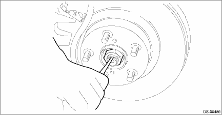
2. Remove the axle nut.
CAUTION:
Do not loosen the axle nut while the rear axle is loaded. Doing so may damage the hub unit bearing.
(1) Lift the crimped section of axle nut.
(2) Remove the axle nut using a socket wrench while depressing the brake pedal.
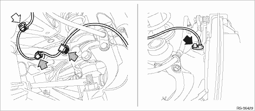
3. Remove the rear ABS wheel speed sensor from the rear axle housing.
(1) Remove the bolts, and remove the rear ABS wheel speed sensor.
(2) Remove the rear ABS wheel speed sensor harness from the upper arm.
CAUTION:
• Be careful not to damage the sensor.
• Do not apply excessive force to the sensor harness.
• Leave the sensor harness clamp (white arrow) on the vehicle side.
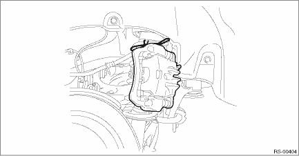
4. Remove the caliper body assembly from the rear axle housing.
(1) Remove the bolts and then remove the brake hose bracket and caliper body assembly.
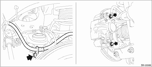
(2) Prepare wiring harnesses etc. to be discarded, and suspend the caliper body assembly from the strut assembly.
5. Remove the rear disc rotor.
NOTE:
If it is difficult to remove the rear disc rotor, perform the following two methods in order.
(1) Remove the adjusting hole cover (A), insert the flat tip screwdriver, and rotate the adjuster assembly - rear brake until the brake shoe moves far enough to remove the disc rotor.
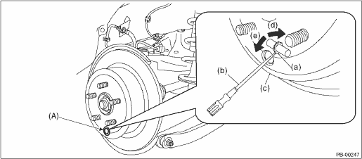
(a) | Adjuster ASSY - rear brake | (c) | Disc rotor | (e) | Shorten the adjuster ASSY - rear brake |
(b) | Flat tip screwdriver | (d) | Extend the adjuster ASSY - rear brake |
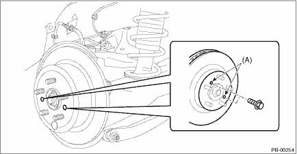
(2) If the disc rotor is not removed after performing above step, screw in an 8 mm (0.31 in) bolt to the threaded part (A) of the disc rotor, and remove the disc rotor.
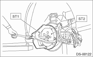
6. Remove the bolt from the rear axle housing, and remove the rear hub unit bearing.
CAUTION:
• Be careful not to damage the magnetic encoder.
• Do not get closer the tool which charged magnetism to magnetic encoder.
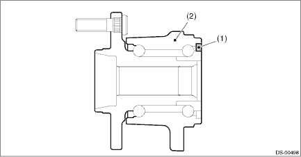
(1) | Magnetic encoder | (2) | Rear hub unit bearing |
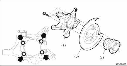
(a) | Rear axle housing | (b) | Rear brake back plate | (c) | Rear hub unit bearing |
NOTE:
If it is hard to remove, use the ST.
Preparation tool:
ST1: AXLE SHAFT PULLER (926470000)
ST2: AXLE SHAFT PULLER PLATE (28099PA110)
 Assembly
DRIVE SHAFT SYSTEM > Rear Hub Unit BearingASSEMBLY1. Install the rear hub unit bearing to the ST securely.Preparation tool:ST: HUB STAND (927080000)(1)Rear hub unit bearing2. Using a press, press n ...
 Disassembly
DRIVE SHAFT SYSTEM > Rear Hub Unit BearingDISASSEMBLYUsing the ST or a hydraulic press, push out the hub bolt (b) from the rear hub unit bearing (a).CAUTION:• Be careful not to hammer the hub ...
Other materials:
Inspection mode Operation
Blind Spot Detection/Rear Cross Traffic Alert (DIAGNOSTICS) > Inspection ModeOPERATIONIt is possible to diagnose the DTC by performing the indicated inspection mode. After correcting the DTC, perform a necessary inspection mode and make sure that the function is resumed correctly and the DTC is r ...
Read current data Operation
OCCUPANT DETECTION SYSTEM (DIAGNOSTICS) > Read Current DataOPERATIONCheck the operating condition of each sensor in the event of malfunction in the seat belt buckle switch, or when the seat belt buckle switch has been replaced.NOTE:For detailed operation procedures, refer to “Application he ...
Dtc p0013 "b" camshaft position actuator control circuit/open bank 1
ENGINE (DIAGNOSTICS)(H4DO) > Diagnostic Procedure with Diagnostic Trouble Code (DTC)DTC P0013 "B" CAMSHAFT POSITION ACTUATOR CONTROL CIRCUIT/OPEN BANK 1DTC detecting condition:Immediately at fault recognitionTrouble symptom:Improper idlingCAUTION:After servicing or replacing faulty part ...
