Subaru Crosstrek Service Manual: Inspection
VEHICLE DYNAMICS CONTROL (VDC) > Rear ABS Wheel Speed Sensor
INSPECTION
1. CHECK WITH SUBARU SELECT MONITOR
1. Connect the Subaru Select Monitor.
NOTE:
For detailed operation procedures, refer to “Application help”.
(1) On «Start» display, select «Diagnosis».
(2) On «Vehicle selection» display, input the target vehicle information and select «Confirmed».
(3) On «Main Menu» display, select «Each System».
(4) On «Select System» display, select «Brake Control System» and select «Enter».
(5) On «Select Function» display, select «Data Monitor».
(6) From the data monitor item list, select «RR Wheel Speed» and «RL Wheel Speed».
2. Check if the speed indicated on the display changes in the same manner as the speedometer reading during acceleration/deceleration when the steering wheel is in the straight-ahead position.
3. If the speed indicated on the display does not change in the inspection, check the ABS wheel speed sensor. Front ABS Wheel Speed Sensor > INSPECTION">
2. CHECK ABS WHEEL SPEED SENSOR UNIT
1. Visually check the tip of the ABS wheel speed sensor for foreign particles or damage. If necessary, clean the tip or replace the ABS wheel speed sensor.
2. Disconnect the ABS wheel speed sensor connector.
3. Check the ABS wheel speed sensor cable for discontinuity. If defective, replace the ABS wheel speed sensor.
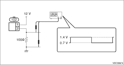
4. Connect a 12 V power supply to No. 1 terminal of ABS wheel speed sensor connector, then attach resistance to the No. 2 terminal. Rotate the wheel at about 2.75 km/h (2 MPH), and measure the voltage using an oscilloscope.
Standard value of output voltage:
0.7 — 1.4 V
5. Replace the ABS wheel speed sensor if the inspection result is not within the standard value.

 Removal
VEHICLE DYNAMICS CONTROL (VDC) > Rear ABS Wheel Speed SensorREMOVAL1. 5 DOOR MODEL1. Disconnect the ground cable from battery.2. Lift up the vehicle, and then remove the rear wheels.3. Remove the r ...
Other materials:
Dtc p2005 tgv control stuck open bank 2
ENGINE (DIAGNOSTICS)(H4DO) > Diagnostic Procedure with Diagnostic Trouble Code (DTC)DTC P2005 TGV CONTROL STUCK OPEN BANK 2DTC DETECTING CONDITION:Immediately at fault recognitionCAUTION:After servicing or replacing faulty parts, perform Clear Memory Mode Clear Memory Mode > OPERATION"&g ...
Dtc u0073 control module communication bus off
AUTO HEADLIGHT BEAM LEVELER SYSTEM (DIAGNOSTICS) > Diagnostic Procedure with Diagnostic Trouble Code (DTC)DTC U0073 CONTROL MODULE COMMUNICATION BUS OFFDetected when CAN line abnormality is detected.NOTE:Perform the diagnosis for LAN system. Basic Diagnostic Procedure > PROCEDURE"> ...
Disassembly
CONTINUOUSLY VARIABLE TRANSMISSION(TR580) > Transfer Driven GearDISASSEMBLY1. Remove the ball bearing using ST.ST1 498077400BEARING REMOVERST2 899864100REMOVER ...
