Subaru Crosstrek Service Manual: Removal
DRIVE SHAFT SYSTEM > Rear Drive Shaft
REMOVAL
1. Disconnect the ground cable from battery. NOTE">
2. Lift up the vehicle, and then remove the rear wheels.
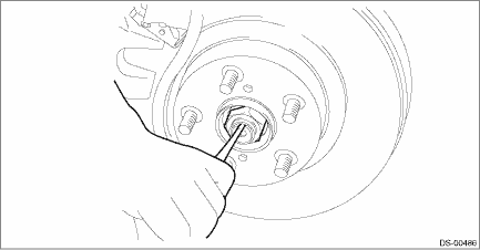
3. Remove the axle nut.
CAUTION:
Do not loosen the axle nut while the rear axle is loaded. Doing so may damage the hub unit bearing.
(1) Lift the crimped section of axle nut.
(2) Remove the axle nut using a socket wrench while depressing the brake pedal.
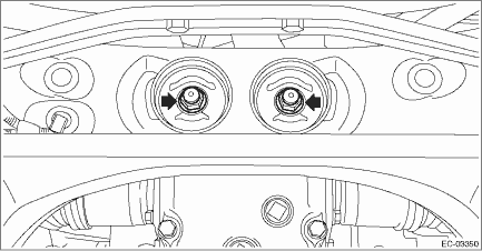
4. Remove the sensor assembly - headlight beam leveler. (Model with auto headlight beam leveler)
CAUTION:
Do not apply impact to the sensor assembly - headlight beam leveler or forcibly move the arm. Doing so may cause sensor damage and malfunction.
(1) Disconnect the connector of the sensor assembly - headlight beam leveler.
(2) Remove the nuts, and remove the sensor assembly - headlight beam leveler.
5. Drain differential gear oil.
6. Remove the propeller shaft. Propeller Shaft > REMOVAL">
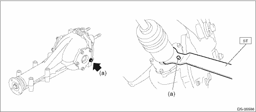
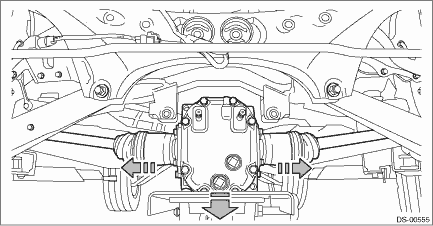
7. Loosen the joint of rear differential assembly and rear drive shaft assembly.
• T type: Pull out the rear drive shaft assembly by fitting the ST to the bolt (a) as shown in the figure.
CAUTION:
Fit the ST to the bolts as shown in the figure to prevent damage of the side bearing retainer.
Preparation tool:
ST: DRIVE SHAFT REMOVER (28099PA100)
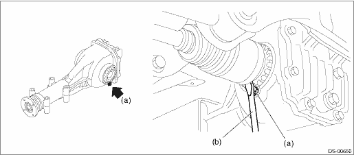
• VA1 type: Pull out the rear drive shaft assembly by fitting the tire lever (b) to the bolt (a) as shown in the figure.
CAUTION:
To prevent damage to the side bearing retainer, use by placing the tire lever against the bolt as shown in the figure.
Preparation tool:
Tire lever
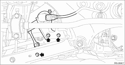
8. Remove the installation section of rear differential assembly.
(1) Support the rear differential assembly with a transmission jack.
(2) Remove the bolts which hold the rear differential front crossmember from the rear sub frame assembly.
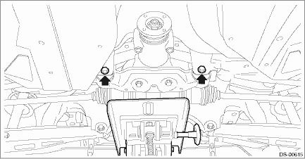
(3) Remove the self-locking nuts which hold the rear differential to the rear sub frame assembly.
9. Completely pull out the rear drive shaft assembly while lowering the rear differential.
CAUTION:
Pay attention to avoid damaging the boot of drive shaft.
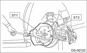
10. Remove the rear drive shaft assembly from the rear axle housing.
NOTE:
If it is hard to remove, use the ST.
Preparation tool:
ST1: AXLE SHAFT PULLER (926470000)
ST2: AXLE SHAFT PULLER PLATE (28099PA110)
 Assembly
DRIVE SHAFT SYSTEM > Rear Drive ShaftASSEMBLYCAUTION:Wrap shaft splines with vinyl tape to protect the boot from scratches.NOTE:Use specified grease.Grease:BJ, EBJ side: NKG814DOJ side: NKG8141. In ...
 Disassembly
DRIVE SHAFT SYSTEM > Rear Drive ShaftDISASSEMBLY1. Remove the outer race (DOJ) from the shaft assembly.CAUTION:Be careful not to damage the boot.(1) Using a flat tip screwdriver or pliers, loosen t ...
Other materials:
Dtc c0056 g sensor abnormal
VEHICLE DYNAMICS CONTROL (VDC) (DIAGNOSTICS) > Diagnostic Procedure with Diagnostic Trouble Code (DTC)DTC C0056 G SENSOR ABNORMALDTC DETECTING CONDITION:Longitudinal G sensor signal failureTROUBLE SYMPTOM:• ABS does not operate.• VDC does not operate.• EyeSight does not operate. ...
If you have accidentally triggered the alarm system
To stop the alarm
Do any of the following operations
Press any button on the access key/
remote transmitter.
Turn the ignition switch to the "ON"
position (models without "keyless access
with push-button start system").
Turn the push-button ignition to the
"ACC" position (models wit ...
Removal
FUEL INJECTION (FUEL SYSTEMS)(H4DO) > Engine Control Module (ECM)REMOVAL1. Disconnect the ground cable from battery.2. Remove the glove box. Glove Box > REMOVAL">3. Disconnect the connector from ECM.4. Remove the bolts and nuts, and remove the ECM. ...
