Subaru Crosstrek Service Manual: Removal
FRONT SUSPENSION > Front Crossmember
REMOVAL
CAUTION:
• The power steering control module continues to operate after the engine stops and calculate the temperature in the control module. Therefore, before starting service of the power steering system which requires disconnection of the connector, stop the engine and allow approx. 30 minutes until the control module becomes cold.
• Before removal or installation, be sure to remove any foreign matter (dust, moisture, oil, etc.) from the power steering control module connector.
1. Disconnect the ground cable from battery. NOTE">
2. Adjust the tilt position of the steering column to the lowest position and lock the tilt lever.
3. Lift up the vehicle, and then remove the front wheels.
4. Remove the under cover - front. Front Under Cover > REMOVAL">
5. Remove the universal joint assembly - steering. Universal Joint > REMOVAL">
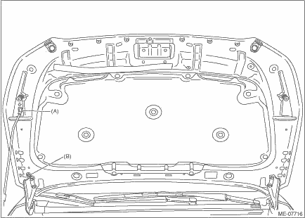
6. Change the front hood stay position from (A) to (B), and completely open the front hood.
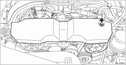
7. Remove the V-belt covers.
8. Disconnect the connector and harness clamp from power steering control module.
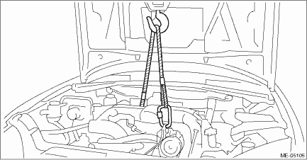
9. Support the engine with a lifting device and wire ropes.
(1) Support the engine with a lifting device and wire ropes.
(2) While lifting up the vehicle, also raise up the lifting device.
CAUTION:
When lifting up the vehicle, raise up wire ropes at the same time.
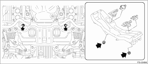
10. Remove the nuts which secure the engine mounting.
(1) Raise up the lifting device, and lift the engine by approx. 10 mm (0.39 in).
(2) Remove the nuts which secure the engine mounting to the front crossmember assembly.
11. Remove the front exhaust pipe. Front Exhaust Pipe > REMOVAL">
12. Remove the front crossmember support. Front Crossmember Support Plate > REMOVAL">
13. Remove the front stabilizer. Front Stabilizer > REMOVAL">
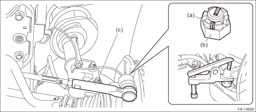
14. Disconnect the tie-rod end.
(1) Pull out the cotter pin (a).
(2) Remove the castle nut (b).
(3) Using a tie-rod end puller, remove the tie-rod end (c).
Preparation tool:
Tie-rod end puller
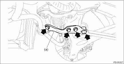
15. Remove the support plate - front crossmember (a).
16. Remove the front arm assembly. Front Arm > REMOVAL">
17. Support the front crossmember assembly using a jack, and remove the bolts which hold the crossmember on the body.
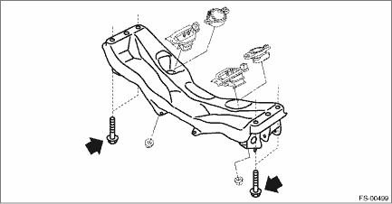
18. Slowly lower the front crossmember assembly with the steering gearbox assembly as a single unit.
CAUTION:
When removing the crossmember, make sure that the tie-rod end does not interfere with the drive shaft boot.
19. Remove the steering gearbox assembly from the front crossmember assembly.
 Installation
FRONT SUSPENSION > Front CrossmemberINSTALLATION1. Check the crossmember for damage or cracks, and correct or replace if defective.2. Install the universal joint assembly - steering. Universal Joi ...

Other materials:
Caution
INTAKE (INDUCTION)(H4DO) > General DescriptionCAUTION• Prior to starting work, pay special attention to the following:1. Always wear work clothes, a work cap, and protective shoes. Additionally, wear a helmet, protective goggles, etc. if necessary.2. Protect the vehicle using a seat cover, ...
Dtc u0100 lost communication with ecm/pcm a
TELEMATICS SYSTEM (DIAGNOSTICS) > Diagnostic Procedure with Diagnostic Trouble Code (DTC)DTC U0100 LOST COMMUNICATION WITH ECM/PCM “A”Detected when CAN data from ECM does not arrive.NOTE:Perform the diagnosis for LAN system. Basic Diagnostic Procedure > PROCEDURE"> ...
Dtc c1231 rear right abs sensor circuit
VEHICLE DYNAMICS CONTROL (VDC) (DIAGNOSTICS) > Diagnostic Procedure with Diagnostic Trouble Code (DTC)DTC C1231 REAR RIGHT ABS SENSOR CIRCUITNOTE:For the diagnostic procedure, refer to “DTC C1241 REAR LEFT ABS SENSOR CIRCUIT”. Diagnostic Procedure with Diagnostic Trouble Code (DTC) & ...
