Subaru Crosstrek Service Manual: Installation
FRONT SUSPENSION > Front Crossmember
INSTALLATION
1. Check the crossmember for damage or cracks, and correct or replace if defective.
2. Install the universal joint assembly - steering. Universal Joint > INSTALLATION">
3. Install each part in the reverse order of removal.
CAUTION:
• Use a new bolt and self-locking nut. For parts which are not reusable, refer to “COMPONENT”. General Description > COMPONENT">
• Always tighten the bushing in the state where the vehicle is at curb weight and the wheels are in full contact with the ground.
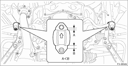
• Install the clamp - stabilizer bushing with the arrow mark facing the front of the vehicle.
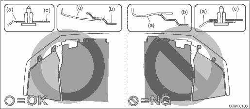
• Install so that the front end of the under cover (b) comes inside the bumper face - front (a), and the front end of the mud guard (c) comes outside the bumper face - front (a).
Tightening torque:
Engine mounting to Front crossmember assembly: General Description > COMPONENT">
Universal joint assembly - steering: 24 N·m (2.45 kgf-m, 17.7 ft-lb)
V-belt cover: 7.5 N·m (0.76 kgf-m, 5.5 ft-lb)
Under cover - front: 18 N·m (1.84 kgf-m, 13.3 ft-lb)
Front suspension parts: General Description > COMPONENT">
When tightening the castle nut, tighten the castle nut to the specified torque first, then tighten it further but within 60° until the hole in the ball stud is aligned with a slot in castle nut.
4. Install the front wheels.
Tightening torque:
Except for C4 model: 120 N·m (12.24 kgf-m, 88.5 ft-lb)
C4 model: 100 N·m (10.20 kgf-m, 73.8 ft-lb)
5. Inspect the wheel alignment and adjust if necessary.
• Inspection: Wheel Alignment > INSPECTION">
• Adjustment: Wheel Alignment > ADJUSTMENT">
CAUTION:
If the steering wheel and steering angle sensor are removed, perform the following VDC setting mode.
– Model without EyeSight: VDC sensor midpoint setting mode VDC Control Module and Hydraulic Control Unit (VDCCM&H/U) > ADJUSTMENT">
– Model with EyeSight: Neutral of Steering Angle Sensor & Lateral G Sensor 0 point setting VDC Control Module and Hydraulic Control Unit (VDCCM&H/U) > ADJUSTMENT">
– Model with EyeSight: Longitudinal G sensor & lateral G sensor 0 point setting VDC Control Module and Hydraulic Control Unit (VDCCM&H/U) > ADJUSTMENT">
6. Perform reinitialization of the auto headlight beam leveler system. (Model with auto headlight beam leveler) Auto Headlight Beam Leveler System > PROCEDURE">

 Removal
FRONT SUSPENSION > Front CrossmemberREMOVALCAUTION:• The power steering control module continues to operate after the engine stops and calculate the temperature in the control module. Therefo ...
Other materials:
Disassembly
MANUAL TRANSMISSION AND DIFFERENTIAL(5MT) > Reverse Check SleeveDISASSEMBLY1. Cover the reverse check sleeve with cloth, and remove the snap ring by using screwdriver.NOTE:If the snap ring is deformed or the spring repulsive force is not enough, replace with a new snap ring.(A)Snap ring2. Remove ...
Selecting a channel from the list
1. The categories list is displayed via
either of the following procedures.
When you touch the
tab in the
SiriusXM main screen (if the list that
was displayed the last time is Categories).
When you select the tab in
each
list screen.
2. Each channel list is displayed whe ...
Automatic headlight beam leveler warning light (models with HID headlights)
This
light illuminates when the automatic
headlight beam leveler does not operate
normally.
If this light illuminates while driving or does
not turn off approximately 3 seconds after
turning the ignition switch to the "ON"
position, have your vehicle inspected at
your SUBARU dealer.
Fr ...
