Subaru Crosstrek Service Manual: Disassembly
DRIVE SHAFT SYSTEM > Rear Drive Shaft
DISASSEMBLY
1. Remove the outer race (DOJ) from the shaft assembly.
CAUTION:
Be careful not to damage the boot.
(1) Using a flat tip screwdriver or pliers, loosen the boot band on the large end of boot (DOJ).
CAUTION:
Be careful not to damage the boot.
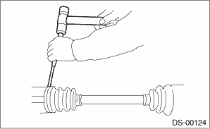
(2) Remove the boot band on the small end of boot (DOJ) in the same manner.
(3) Remove the large end of boot (DOJ) from outer race (DOJ).
(4) Remove the round snap ring at the neck of outer race (DOJ) with a flat tip screwdriver.
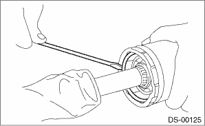
(5) Remove the outer race (DOJ) from the shaft assembly.
(6) Wipe off the grease and take out the ball bearings.
CAUTION:
The grease is a special grease (grease for constant velocity joints). Do not mix with other greases.
NOTE:
Disassemble the parts taking care not to lose balls.
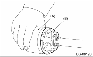
(A) | Outer race (DOJ) |
(B) | Grease |
2. Remove the cage from the inner race.
(1) Turn the cage by a half pitch to the track groove of inner race and shift the cage.
(2) Using pliers, remove the snap ring fixing the inner race to the shaft.
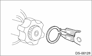
(3) Take out the inner race.
(4) Remove the cage from the shaft and remove the boot (DOJ).
CAUTION:
Wrap shaft splines with vinyl tape to protect the boot from scratches.
3. Remove the boot (BJ) or boot (EBJ) in the same procedure as the boot (DOJ).
NOTE:
Further disassembly of the drive shaft is impossible because the BJ and EBJ cannot be disassembled.
 Removal
DRIVE SHAFT SYSTEM > Rear Drive ShaftREMOVAL1. Disconnect the ground cable from battery. NOTE">2. Lift up the vehicle, and then remove the rear wheels.3. Remove the axle nut.CAUTION:Do not ...
 Inspection
DRIVE SHAFT SYSTEM > Rear Drive ShaftINSPECTIONCheck the removed parts for damage, wear, corrosion etc. Repair or replace if defective.• DOJ (Double Offset Joint):Check for seizure, corrosion ...
Other materials:
Operation
VEHICLE DYNAMICS CONTROL (VDC) > ABS Sequence ControlOPERATION1. While the ABS sequence control is being performed, the operation of the hydraulic unit can be checked using the brake tester or pressure gauge after the hydraulic unit solenoid valve operation.2. ABS sequence control can be started ...
Airbag warning light illumination pattern Inspection
OCCUPANT DETECTION SYSTEM (DIAGNOSTICS) > Airbag Warning Light Illumination PatternINSPECTIONTurn the ignition switch to ON, and confirm that the airbag warning light remains on for approx. 6 seconds then turns off afterwards.(1)Airbag warning light(2)Approx. 6 seconds(3)Ignition switch ON ...
Bottle holders
CAUTION
Do not pick up a bottle from the
bottle holder or put a bottle in the
holder while you are driving, as
this may distract you and lead to
an accident.
When placing a beverage in a
bottle holder, make sure it is
capped. Otherwise, the beverage
could spill when opening/closi ...
