
Subaru Ascent 2018-2026 Owner's Manual: RAB warning indicator
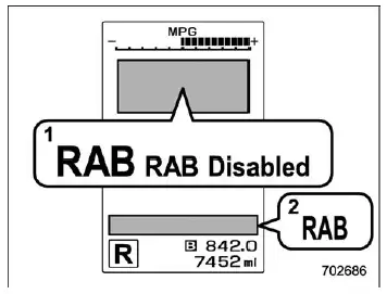
- RAB malfunction message
- RAB warning indicator
If a malfunction occurs within the Reverse Automatic Braking (RAB) system of the Subaru Ascent, the warning indicator and message will illuminate on the combination meter. This serves as an important alert that the system requires attention.
In such situations, you should promptly consult your nearest SUBARU dealer to ensure that the system is inspected and restored to proper working condition.
Handling of the sonar sensors
The Subaru Ascent is equipped with four sonar sensors integrated into the rear bumper. These sensors are essential for the correct operation of the Reverse Automatic Braking system, so proper care and handling are crucial.
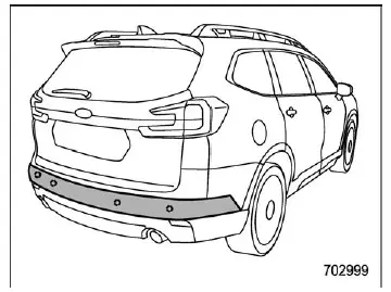
- Avoid placing stickers, decals, or any foreign objects on or near the sonar sensor areas on the rear bumper.
- Always keep the surface around the sensors clean to ensure accurate detection performance in your Subaru Ascent.
- Do not modify or alter the rear bumper structure, as this can disrupt sensor alignment.
- Avoid painting over the areas where the sonar sensors are located.
- Do not use high-pressure water jets directly on the sonar sensors during car washing, as this may damage them.
- Prevent strong impacts to the rear bumper. Even a minor misalignment of the sensors can affect detection accuracy. If an impact occurs, have your Subaru Ascent inspected by a SUBARU dealer as soon as possible.
- Never attempt to disassemble the sonar sensors yourself.
NOTE
If any repair, replacement, repainting, or maintenance is required in the area around the sonar sensors, always contact a qualified SUBARU dealer. Proper handling ensures that the Subaru Ascent continues to deliver reliable and precise RAB system performance.
Additional note: For optimal performance in real-world driving, regularly inspect the rear bumper area of your Subaru Ascent, especially after driving in harsh weather conditions such as snow, mud, or heavy rain, as sensor cleanliness directly impacts system accuracy.
 Reverse Automatic Braking (RAB) system ON/OFF setting
In the Subaru Ascent, when the select lever is moved into the "R" (Reverse) position,
you gain access to customizable settings for the Reverse Automatic Braking (RAB)
system directly thr ...
 Driver Monitoring System
The Driver Monitoring System, known in some markets as DriverFocus, is an advanced
safety and personalization feature integrated into the Subaru Ascent. This intelligent
system continuously observ ...
Other materials:
Dtc p0073 ambient air temperature sensor circuit "a" high
ENGINE (DIAGNOSTICS)(H4DO) > Diagnostic Procedure with Diagnostic Trouble Code (DTC)DTC P0073 AMBIENT AIR TEMPERATURE SENSOR CIRCUIT "A" HIGHNOTE:For the diagnostic procedure, refer to DTC P0072. Diagnostic Procedure with Diagnostic Trouble Code (DTC) > DTC P0072 AMBIENT AIR TEMPERA ...
Certification for keyless access with push-button start system
U.S.-spec. models
FCC ID: HYQ14AHC
FCC ID: HYQ13CZZ
FCC ID: Y8PSSPIMB02
FCC ID: Y8PSSPLF02
CAUTION
FCC WARNING
Changes or modifications not expressly
approved by the party responsible
for compliance could void
the user's authority to operate the
equipment.
NOTE
This device complies with ...
Dtc p0967 pressure control solenoid "b" control circuit high
CONTINUOUSLY VARIABLE TRANSMISSION (DIAGNOSTICS) > Diagnostic Procedure with Diagnostic Trouble Code (DTC)DTC P0967 PRESSURE CONTROL SOLENOID "B" CONTROL CIRCUIT HIGHDTC detecting condition:Immediately at fault recognitionTrouble symptom:Engine speed increases abruptly, and can not star ...
