Subaru Crosstrek Service Manual: Dtc p0967 pressure control solenoid "b" control circuit high
CONTINUOUSLY VARIABLE TRANSMISSION (DIAGNOSTICS) > Diagnostic Procedure with Diagnostic Trouble Code (DTC)
DTC P0967 PRESSURE CONTROL SOLENOID "B" CONTROL CIRCUIT HIGH
DTC detecting condition:
Immediately at fault recognition
Trouble symptom:
Engine speed increases abruptly, and can not start.
CAUTION:
Use the check board when measuring the TCM terminal voltage and resistance.
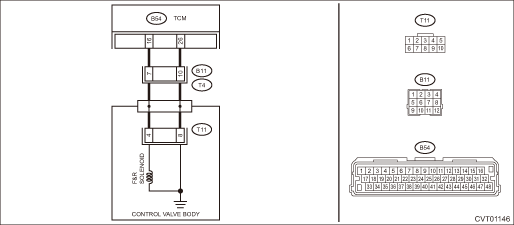
Wiring diagram:
CVT control system CVT Control System">

| STEP | CHECK | YES | NO |
1.CHECK INPUT SIGNAL FOR TCM.
1) After driving with warm up condition, park the vehicle while depressing the brake pedal at “D” range.
2) Read the data of «Commanded Forward & Reverse Linear Solenoid Current» and «Actual Forward & Reverse Linear Solenoid Current» using Subaru Select Monitor.
Does the value of «Commanded Forward & Reverse Linear Solenoid Current» and «Actual Forward & Reverse Linear Solenoid Current» almost correspond?
Check for poor contact of connector.
Diagnostic Procedure with Diagnostic Trouble Code (DTC) > DTC P0967 PRESSURE CONTROL SOLENOID "B" CONTROL CIRCUIT HIGH">Go to Step 2.
2.CHECK HARNESS.
1) Turn the ignition switch to OFF.
2) Disconnect the TCM connector.
3) Disconnect the transmission connector.
4) Measure the resistance between TCM connector and transmission connectors.
Connector & terminal
(B54) No. 16 — (B11) No. 7:
Is the resistance less than 1 ??
Diagnostic Procedure with Diagnostic Trouble Code (DTC) > DTC P0967 PRESSURE CONTROL SOLENOID "B" CONTROL CIRCUIT HIGH">Go to Step 3.
Repair the open circuit of harness.
3.CHECK HARNESS.
1) Turn the ignition switch to ON.
2) Measure the voltage between TCM connector and chassis ground.
Connector & terminal
(B54) No. 16 (+) — Chassis ground (−):
Is the voltage approx. 0 V?
Diagnostic Procedure with Diagnostic Trouble Code (DTC) > DTC P0967 PRESSURE CONTROL SOLENOID "B" CONTROL CIRCUIT HIGH">Go to Step 4.
Repair the short circuit of harness.
4.CHECK F&R SOLENOID.
Measure the resistance between transmission connector and transmission body.
Connector & terminal
(T4) No. 7 — Transmission body:
Is the resistance approx. 4 — 6 ?? (when cold)
Check for poor contact of connector, and if no fault is found, replace the TCM. Transmission Control Module (TCM)">
Diagnostic Procedure with Diagnostic Trouble Code (DTC) > DTC P0967 PRESSURE CONTROL SOLENOID "B" CONTROL CIRCUIT HIGH">Go to Step 5.
5.CHECK HARNESS INSIDE TRANSMISSION.
CAUTION:
Start work after ATF cools down.
1) Remove the transmission valve cover.
2) Check for the harness pinch, damage.
Is there any fault in the harness?
Replace the transmission harness.
Diagnostic Procedure with Diagnostic Trouble Code (DTC) > DTC P0967 PRESSURE CONTROL SOLENOID "B" CONTROL CIRCUIT HIGH">Go to Step 6.
6.CHECK HARNESS INSIDE TRANSMISSION.
1) Disconnect the control valve body connector.
2) Turn the ignition switch to ON.
3) Measure the voltage between transmission connector and transmission body.
Connector & terminal
(T4) No. 7 (+) — Transmission body (−):
Is the voltage approx. 0 V?
Replace the control valve body. Control Valve Body">
Replace the transmission harness.
1. OUTLINE OF DIAGNOSIS
• Detect open circuit or power supply-output short circuit in the transmission forward/reverse clutch pressure solenoid circuit.
• Judge as NG if the transmission forward/reverse clutch pressure solenoid drive current is lower than the predetermined value.
2. EXECUTION CONDITION
Secondary Parameters | Execution condition |
12 V battery system voltage | ≥ 9 V |
Target forward & reverse clutch pressure control solenoid current | ≥ 0.3 A |
3. DIAGNOSTIC METHOD
If the duration of time while the following conditions are met is longer than the time indicated, judge as NG.
Malfunction Criteria | Threshold Value |
Signal of malfunction from solenoid driver IC | ON |
As defined by: | |
Measured forward & reverse clutch pressure control solenoid current < 5.9 mA |
Time Needed for Diagnosis: 1 second
Malfunction Indicator Light Illumination: Illuminates as soon as a malfunction occurs.
 Dtc p0966 pressure control solenoid "b" control circuit low
CONTINUOUSLY VARIABLE TRANSMISSION (DIAGNOSTICS) > Diagnostic Procedure with Diagnostic Trouble Code (DTC)DTC P0966 PRESSURE CONTROL SOLENOID "B" CONTROL CIRCUIT LOWDTC detecting conditio ...
 Dtc p0970 pressure control solenoid "c" control circuit low
CONTINUOUSLY VARIABLE TRANSMISSION (DIAGNOSTICS) > Diagnostic Procedure with Diagnostic Trouble Code (DTC)DTC P0970 PRESSURE CONTROL SOLENOID "C" CONTROL CIRCUIT LOWDTC detecting conditio ...
Other materials:
Caution
ENGINE (DIAGNOSTICS)(H4DO) > General DescriptionCAUTION1. Airbag system wiring harness is routed near the ECM, main relay and fuel pump relay.CAUTION:• Do not use electrical test equipment on the airbag system circuits.• Be careful not to damage the airbag system wiring harness when s ...
Caution
DIFFERENTIALS > General DescriptionCAUTION• When performing any work, always wear work clothes, a work cap and protective shoes. Additionally, wear a helmet, protective goggles, etc. if necessary.• Remove contamination including dirt and corrosion before removal, installation, disasse ...
Dtc b161a lost communication with front satellite sensor bus
AIRBAG SYSTEM (DIAGNOSTICS) > Diagnostic Chart with Trouble CodeDTC B161A LOST COMMUNICATION WITH FRONT SATELLITE SENSOR BUSDiagnosis start condition:Ignition voltage is 10 V to 16 V.DTC detecting condition:• Harness between airbag control module and front sub sensor is open or shorted.&bul ...
