Subaru Crosstrek Service Manual: Procedure
HVAC SYSTEM (HEATER, VENTILATOR AND A/C) > Refrigerant Pressure with Manifold Gauge Set
PROCEDURE
1. REFRIGERANT GAS PRESSURE INSPECTION
1. Prepare the vehicle.
NOTE:
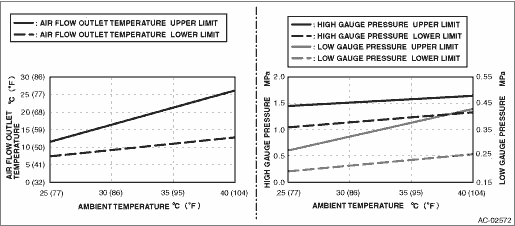
Check that the ambient temperature is 25 — 40°C (77 — 104°F) and that the humidity is 30% — 80%.
• Place the vehicle in the shade and windless condition, and open the front hood.
• Open the front windows and close all doors.
2. Check the refrigerant pressure.
Preparation tool:
Manifold gauge set
(1) Connect the manifold gauge set, and start the engine.
(2) Set the vehicle to the following conditions.
Item | Condition |
Engine | Warmed up (Engine coolant temperature indicator light: OFF) |
Air vent grille | Shutter is fully open. |
A/C switch | ON |
Temperature adjustment dial | LO (MAX COOL) |
FRESH/RECIRC switch | RECIRC |
Air flow control dial or switch | VENT |
Fan dial | Auto A/C model: 5/7 level |
Manual A/C model: 3/4 level |
(3) In the condition of step (2), idle the engine for 30 minutes.
(4) Read the gauge values on both high pressure side and low pressure side for manifold gauge.
3. Measure the air vent grille outlet opening temperature, ambient temperature and humidity.
Preparation tool:
Thermometer and hygrometer
NOTE:
For outlet opening temperature, measure the average temperature of center grille assembly and side grille assembly.
4. Check that the high and low pressures and outlet opening temperature for ambient temperature and humidity is within the standard value described in the chart below.
5. Refer to “DIAGNOSIS WITH SYMPTOM” if the inspection result is not within the standard value. Refrigerant Pressure with Manifold Gauge Set > INSPECTION">
 Inspection
HVAC SYSTEM (HEATER, VENTILATOR AND A/C) > Refrigerant Pressure with Manifold Gauge SetINSPECTION1. INSPECTION WITH PRESSURE SYMPTOMSSymptomsReferenceBoth high and low pressure sides are low. Refri ...
 Relay and fuse
...
Other materials:
General settings
Touch the tab for the audio unit
basic
settings.
Item
Function
System
Language
Select to change the language
Button
Beeps
Select to set the sound beeps
on/off.
System
Software
Select to update software versions.
This menu is not ...
Assembly
MANUAL TRANSMISSION AND DIFFERENTIAL(5MT) > Transfer Driven GearASSEMBLY1. Using the ST, install the taper roller bearing (transfer case side).CAUTION:Do not apply a load in excess of 10 kN (1 ton, 1.1 US ton, 1.0 Imp ton).NOTE:Be careful when handling, because the outer race and inner race of th ...
Operation
VEHICLE DYNAMICS CONTROL (VDC) (DIAGNOSTICS) > Subaru Select MonitorOPERATION1. HOW TO USE SUBARU SELECT MONITORFor detailed operation procedures, refer to “Application help”.2. READ CURRENT DATA1. On «Start» display, select «Diagnosis».2. On «Vehicle selection» display, input t ...
