Subaru Crosstrek Service Manual: Operation
VEHICLE DYNAMICS CONTROL (VDC) > VDC Sequence Control
OPERATION
1. While the VDC sequence control is performed, the operation of the hydraulic unit can be checked using the brake tester or pressure gauge after the hydraulic unit solenoid valve is operated.
2. VDC sequence control can be started by Subaru Select Monitor.
1. VDC SEQUENCE CONTROL WITH SUBARU SELECT MONITOR
NOTE:
In the event of any trouble, sequence control will not operate.
1. Connect the Subaru Select Monitor to data link connector.
NOTE:
For detailed operation procedures, refer to “Application help”.
(1) Turn the ignition switch to ON.
(2) On «Start» display, select «Diagnosis».
(3) On «Vehicle selection» display, input the target vehicle information and select «Confirmed».
(4) On «Main Menu» display, select «Each System».
(5) On «Select System» display, select «Brake Control System» and select «Enter».
(6) On «Select Function» display, select «Work Support».
(7) From the work support item list, select «VDC Function Check Mode».
2. Operate according to the procedures displayed in the Subaru Select Monitor.
3. The brake system being operated is displayed on the Subaru Select Monitor.
2. CONDITIONS FOR VDC SEQUENCE CONTROL
NOTE:
The control operation starts at point A.
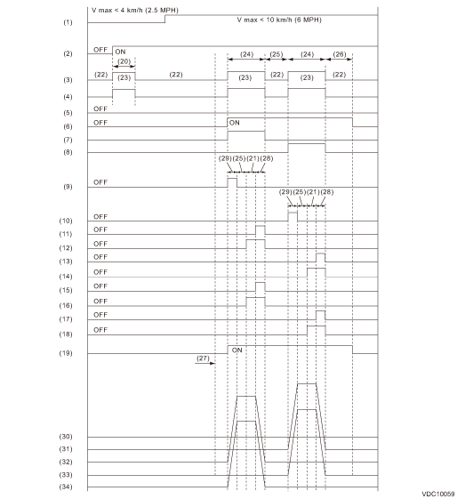
(1) | All wheel speed | (13) | FR decompression valve | (25) | 1 second |
(2) | Ignition key | (14) | FR compression valve | (26) | 1.6 seconds |
(3) | ABS warning light | (15) | RR decompression valve | (27) | Point A |
(4) | VDC warning light | (16) | RR compression valve | (28) | 0.4 seconds |
(5) | Switch - stop light | (17) | RL decompression valve | (29) | 0.8 seconds |
(6) | Valve relay | (18) | RL compression valve | (30) | Master cylinder pressure |
(7) | VDC switching valve 1 FL | (19) | Pump motor | (31) | FR wheel cylinder pressure |
(8) | VDC switching valve 1 FR | (20) | A few seconds | (32) | FL wheel cylinder pressure |
(9) | VDC switching valve 2 FL | (21) | 1.2 seconds | (33) | RL wheel cylinder pressure |
(10) | VDC switching valve 2 FR | (22) | Light OFF | (34) | RR wheel cylinder pressure |
(11) | FL decompression valve | (23) | Light ON | ||
(12) | FL compression valve | (24) | 3.4 seconds |

 Specification
VEHICLE DYNAMICS CONTROL (VDC) > VDC Sequence ControlSPECIFICATION1. CONDITIONS FOR COMPLETION OF VDC SEQUENCE CONTROLWhen the following conditions develop, the VDC sequence control stops and VDC o ...
Other materials:
Dtc u0420 invalid data received from power steering control module
LAN SYSTEM (DIAGNOSTICS) > Diagnostic Procedure with Diagnostic Trouble Code (DTC)DTC U0420 INVALID DATA RECEIVED FROM POWER STEERING CONTROL MODULEDTC DETECTING CONDITION:Defective data was transmitted from EPS CM.TROUBLE SYMPTOM:Cooperation control with EPS CM does not operate properly.STEPCHEC ...
Replacement
DIFFERENTIALS > Rear Differential Front Oil SealREPLACEMENT1. Shift the select lever or gear shift lever to neutral.2. Release the parking brake.3. Disconnect the ground cable from battery.4. Lift up the vehicle.5. Drain differential gear oil. Differential Gear Oil > REPLACEMENT">6. R ...
Tire replacement
The tires and wheels of your Subaru Ascent are carefully selected to match the
vehicle’s design characteristics, ensuring optimal handling, comfort, and durability.
Replacing them with incorrect specifications can negatively impact performance and
safety.
Always use tires that match the ori ...
