Subaru Crosstrek Service Manual: Dtc b1572 imm circuit except antenna circuit
KEYLESS ACCESS WITH PUSH BUTTON START SYSTEM (DIAGNOSTICS) > Diagnostic Procedure with Diagnostic Trouble Code (DTC)
DTC B1572 IMM CIRCUIT EXCEPT ANTENNA CIRCUIT
1. EXCEPT FOR C0 AND C5 MODELS
DTC detecting condition:
Communication error between keyless access CM and ECM
Trouble symptom:
Engine will not start.
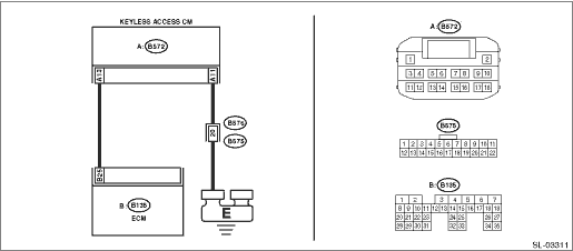
Wiring diagram:
Push button start system Push Button Start System > WIRING DIAGRAM">
| STEP | CHECK | YES | NO |
1.CHECK GROUNDING POINT.
Check the grounding point of the engine ground and chassis ground.
Are there any loose connections, any foreign objects caught in the ground lines or contact surface, or any fluid stains?
Remove the foreign matters, and tighten to the specified torque. Then start the engine, and check that the fault was removed. Check DTC Read Diagnostic Trouble Code (DTC)">, and when DTC B1572 is still displayed, Diagnostic Procedure with Diagnostic Trouble Code (DTC) > DTC B1572 IMM CIRCUIT EXCEPT ANTENNA CIRCUIT">Go to Step 2.
Diagnostic Procedure with Diagnostic Trouble Code (DTC) > DTC B1572 IMM CIRCUIT EXCEPT ANTENNA CIRCUIT">Go to Step 2.
2.CHECK CURRENT DATA.
1) Turn the ignition switch to ON.
2) Check the current data display of «Keyless Access with Push Button Start» using Subaru Select Monitor. Read Current Data">
3) Display the next data. “Immobilizer” “Engine start” “Unlock confirmation”
Data
Immobilizer = Unset:
Engine start = Engine start permission:
Unlock confirmation = Confirmed:
Is the data displayed as indicated on the left?
Diagnostic Procedure with Diagnostic Trouble Code (DTC) > DTC B1572 IMM CIRCUIT EXCEPT ANTENNA CIRCUIT">Go to Step 3.
Perform diagnostics with phenomenon. Diagnostics with Phenomenon > INSPECTION">
3.CHECK CURRENT DATA.
Use the Subaru Select Monitor to check the current data of «Keyless Access with Push Button Start» when holding down the push button ignition switch while depressing on the brake pedal. Read Current Data">
Data
EGI code reception status = Reception:
NOTE:
If “Reception” is displayed, the status changes to “Not yet received” in 10 seconds. When performing the check again, perform the check after turning the ignition to OFF.
Is the data displayed as indicated on the left?
Diagnostic Procedure with Diagnostic Trouble Code (DTC) > DTC B1572 IMM CIRCUIT EXCEPT ANTENNA CIRCUIT">Go to Step 4.
Repair or replace the harness between keyless access CM and ECM.
4.CHECK WIRING HARNESS.
1) Turn the ignition switch to OFF.
2) Disconnect the keyless access CM connector and ECM connector.
3) Using a tester, measure the resistance between the keyless access CM connector and ECM.
Connector & terminal
(B572) No. 13 — (B135) No. 25:
Is the resistance less than 10 ??
Diagnostic Procedure with Diagnostic Trouble Code (DTC) > DTC B1572 IMM CIRCUIT EXCEPT ANTENNA CIRCUIT">Go to Step 5.
Repair or replace the open circuit of harness.
5.CHECK WIRING HARNESS.
Using a tester, measure the resistance between the keyless access CM connector and chassis ground.
Connector & terminal
(B572) No. 11 — Chassis ground:
Is the resistance less than 10 ??
Diagnostic Procedure with Diagnostic Trouble Code (DTC) > DTC B1572 IMM CIRCUIT EXCEPT ANTENNA CIRCUIT">Go to Step 6.
Repair or replace the open circuit of harness.
6.CHECK ECM.
1) Install the ECM from other normal operating vehicle (with push button start) which use same ECM to the vehicle to be diagnosed.
2) Perform ECM registration. Refer to the “REGISTRATION MANUAL FOR IMMOBILIZER” provided as a separate volume.
Is ECM registration finished? And does the engine start?
Replace the ECM. Engine Control Module (ECM) > REMOVAL"> Install the ECM from other vehicle to the original vehicle.
Replace the keyless access CM. Keyless Access CM">
2. FOR C0 AND C5 MODELS
DTC detecting condition:
Communication error between ID code box and ECM
Trouble symptom:
Engine will not start.
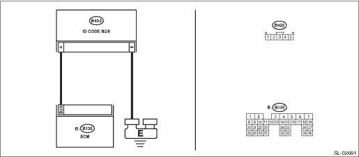
Wiring diagram:
Push button start system Push Button Start System > WIRING DIAGRAM">
| STEP | CHECK | YES | NO |
1.CHECK GROUNDING POINT.
Check the grounding point of the engine ground and chassis ground.
Are there any loose connections, any foreign objects caught in the ground lines or contact surface, or any fluid stains?
Remove the foreign matters, and tighten to the specified torque. Then start the engine, and check that the fault was removed. Check DTC Read Diagnostic Trouble Code (DTC)">, and when DTC B1572 is still displayed, Diagnostic Procedure with Diagnostic Trouble Code (DTC) > DTC B1572 IMM CIRCUIT EXCEPT ANTENNA CIRCUIT">Go to Step 2.
Diagnostic Procedure with Diagnostic Trouble Code (DTC) > DTC B1572 IMM CIRCUIT EXCEPT ANTENNA CIRCUIT">Go to Step 2.
2.CHECK CURRENT DATA.
1) Turn the ignition switch to ON.
2) Check the current data display of «Keyless Access with Push Button Start» using Subaru Select Monitor. Read Current Data">
3) Display the next data. “Immobilizer” “Engine start” “Unlock confirmation”
Data
Immobilizer = Unset:
Engine start = Engine start permission:
Unlock confirmation = Confirmed:
Is the data displayed as indicated on the left?
Diagnostic Procedure with Diagnostic Trouble Code (DTC) > DTC B1572 IMM CIRCUIT EXCEPT ANTENNA CIRCUIT">Go to Step 3.
Perform diagnostics with phenomenon. Diagnostics with Phenomenon > INSPECTION">
3.CHECK CURRENT DATA.
Use the Subaru Select Monitor to check the current data of «Keyless Access with Push Button Start» when holding down the push button ignition switch while depressing on the brake pedal. Read Current Data">
Data
EGI code reception status = Reception:
NOTE:
If “Reception” is displayed, the status changes to “Not yet received” in 10 seconds. When performing the check again, perform the check after turning the ignition to OFF.
Is the data displayed as indicated on the left?
Diagnostic Procedure with Diagnostic Trouble Code (DTC) > DTC B1572 IMM CIRCUIT EXCEPT ANTENNA CIRCUIT">Go to Step 4.
Repair or replace the harness between ID code box and ECM.
4.CHECK WIRING HARNESS.
1) Turn the ignition switch to OFF.
2) Disconnect the ID code box connector and the ECM connector.
3) Using a tester, measure the resistance between ID code box connector and ECM.
Connector & terminal
(B422) No. 4 — (B135) No. 25:
Is the resistance less than 10 ??
Diagnostic Procedure with Diagnostic Trouble Code (DTC) > DTC B1572 IMM CIRCUIT EXCEPT ANTENNA CIRCUIT">Go to Step 5.
Repair or replace the open circuit of harness.
5.CHECK WIRING HARNESS.
Using a tester, measure the resistance between ID code box connector and chassis ground.
Connector & terminal
(B422) No. 5 — Chassis ground:
Is the resistance less than 10 ??
Diagnostic Procedure with Diagnostic Trouble Code (DTC) > DTC B1572 IMM CIRCUIT EXCEPT ANTENNA CIRCUIT">Go to Step 6.
Repair or replace the open circuit of harness.
6.CHECK ECM.
1) Install the ECM from other normal operating vehicle (with push button start) which use same ECM to the vehicle to be diagnosed.
2) Perform ECM registration. Refer to the “REGISTRATION MANUAL FOR IMMOBILIZER” provided as a separate volume.
Is ECM registration finished? And does the engine start?
Replace the ECM. Engine Control Module (ECM) > REMOVAL"> Install the ECM from other vehicle to the original vehicle.
Replace the ID code box. ID Code Box">
 Dtc b27a8 trunk/rear gate external antenna open
KEYLESS ACCESS WITH PUSH BUTTON START SYSTEM (DIAGNOSTICS) > Diagnostic Procedure with Diagnostic Trouble Code (DTC)DTC B27A8 TRUNK/REAR GATE EXTERNAL ANTENNA OPENDTC detecting condition:When open ...
 Dtc b1576 egi control module eeprom
KEYLESS ACCESS WITH PUSH BUTTON START SYSTEM (DIAGNOSTICS) > Diagnostic Procedure with Diagnostic Trouble Code (DTC)DTC B1576 EGI CONTROL MODULE EEPROMDTC detecting condition:• ECM malfunctio ...
Other materials:
Dtc p0453 evap system (cpc) pressure sensor/switch circuit high
ENGINE (DIAGNOSTICS)(H4DO) > Diagnostic Procedure with Diagnostic Trouble Code (DTC)DTC P0453 EVAP SYSTEM (CPC) PRESSURE SENSOR/SWITCH CIRCUIT HIGHDTC detecting condition:Immediately at fault recognitionCAUTION:After servicing or replacing faulty parts, perform Clear Memory Mode Clear Memory Mod ...
Basic diagnostic procedure Procedure
ENGINE (DIAGNOSTICS)(H4DO) > Basic Diagnostic ProcedurePROCEDURE1. ENGINESTEPCHECKYESNO1.CHECK ENGINE START FAILURE.1) Ask the customer when and how the trouble occurred using the interview check list. Check List for Interview > CHECK">2) Start the engine.Does the engine start? Basic ...
Removal
LIGHTING SYSTEM > Front Turn Signal Light BulbREMOVAL1. Disconnect the ground cable from battery. NOTE">2. Turn the steering wheel in the opposite direction from the parts to be removed. Then remove the clips and turn over the mud guard - front.3. Remove the bulb socket and front turn si ...
