
Subaru Crosstrek Service Manual: Intake manifold vacuum Inspection
MECHANICAL(H4DO) > Intake Manifold Vacuum
INSPECTION
1. Turn the ignition switch to OFF.
2. Warm up the engine.
3. Install the vacuum gauge.
(1) Remove the brake booster vacuum hose from the intake manifold.
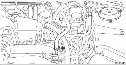
(2) Connect the vacuum gauge to the intake manifold.
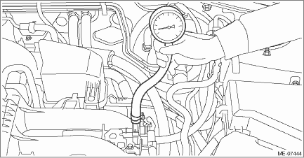
4. Keep the engine at idle speed and read the vacuum gauge indication.
NOTE:
Condition of engine inside can be diagnosed by observing the behavior of the vacuum gauge needle as described in table below.
Intake manifold vacuum (at idling, A/C OFF):
Standard
−60.0 kPa (−450 mmHg, −17.72 inHg) or more
Diagnosis of engine condition by inspection of intake manifold vacuum | |
Vacuum gauge needle behavior | Possible engine condition |
1. Needle is steady but lower than standard value. This tendency becomes more evident as engine temperature rises. | Leakage around intake manifold gasket, disconnection or damage of vacuum hose |
2. Needle intermittently drops to position lower than standard value. | Leakage around cylinder |
3. Needle drops suddenly and intermittently from standard value. | Sticky valve |
4. When engine speed is gradually increased, needle begins to vibrate rapidly at certain speed, and then vibration increases as engine speed increases. | Weak or broken valve springs |
5. Needle vibrates above and below standard value in narrow range. | Defective ignition system |
5. After inspection, install the related parts in the reverse order of removal.
 Intake and exhaust valve Specification
MECHANICAL(H4DO) > Intake and Exhaust ValveSPECIFICATIONRefer to “Cylinder Head” for removal and installation procedures of the intake and exhaust valves. Cylinder Head > REMOVAL&qu ...
 Piston Specification
MECHANICAL(H4DO) > PistonSPECIFICATIONRefer to “Cylinder Block” for removal and installation procedures of pistons. Cylinder Block > REMOVAL"> Cylinder Block > INSTALLAT ...
Other materials:
Steering responsive fog lights warning indicator/ Steering responsive fog
lights OFF indicator (models with EyeSight system)
NOTE
For details about the steering responsive
fog lights system, refer to "Steering
responsive fog lights system (models
with EyeSight system)"
Steering responsive fog lights
warning indicator
This indicator appears when the steering
responsive fog lights system malfunctions.
When this ...
Throttle position sensor Specification
FUEL INJECTION (FUEL SYSTEMS)(H4DO) > Throttle Position SensorSPECIFICATIONThrottle body is a non-disassembled part, so do not remove the throttle position sensor from throttle body.Refer to “Throttle Body” for removal and installation procedure. Throttle Body > REMOVAL"> ...
Dtc p0841 transmission fluid pressure sensor/switch "a" circuit range/performance
CONTINUOUSLY VARIABLE TRANSMISSION (DIAGNOSTICS) > Diagnostic Procedure with Diagnostic Trouble Code (DTC)DTC P0841 TRANSMISSION FLUID PRESSURE SENSOR/SWITCH "A" CIRCUIT RANGE/PERFORMANCEDTC detecting condition:Immediately at fault recognitionTrouble symptom:• Acceleration is poor ...
