Subaru Crosstrek Service Manual: Installation
MECHANICAL(H4DO) > Cylinder Block
INSTALLATION
1. Apply engine oil to the crankshaft bearing, and install the crankshaft bearing to the cylinder block.
CAUTION:
• Place a wood board wrapped with a waste cloth to prevent the knock pin damage and to stabilize the cylinder block before work.
• Be careful not to scratch the mating surface of cylinder block during work.
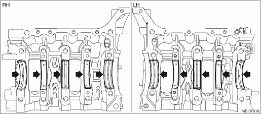
2. Install O-rings to the cylinder block LH.
NOTE:
Use new O-rings.
3. Apply engine oil to the crankshaft journal, and set the crankshaft to cylinder block LH.
4. Apply liquid gasket to the mating surface of cylinder block RH as shown in the figure.
CAUTION:
Do not let the liquid gasket overflow to the oil passage and crankshaft bearing portions, because the engine seizure may result.
NOTE:
• Before applying liquid gasket, degrease the old liquid gasket seal surface of the cylinder block RH and cylinder block LH.
• Install within 5 min. after applying liquid gasket.
Liquid gasket:
THREE BOND 1217G (Part No. K0877Y0100), THREE BOND 1217H or equivalent
Liquid gasket applying diameter:
Mating surfaces other than ranges A and B
1±0.5 mm (0.0394±0.0197 in)
Mating surfaces of ranges A and B
4±0.5 mm (0.1575±0.0197 in)
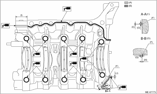
(A) | Range A | (E) | 1 mm (0.0394 in) or less | (I) | 36 mm (1.4173 in) |
(B) | Range B | (F) | Chamfer edge | (J) | 2.5 mm (0.0984 in) |
(C) | Liquid gasket applying position of mating surfaces (other than the edge) of range B | (G) | φ4±0.5 mm (0.1575±0.0197 in) | ||
(D) | Liquid gasket applying position of mating surfaces (the edge) of range B | (H) | 2 mm (0.0787 in) |
5. Install the cylinder block RH to the cylinder block LH.
6. Join the cylinder blocks.
(1) Apply a coat of engine oil to the washers and cylinder block mounting bolt threads.
NOTE:
To prevent mixture of engine oil into the water jacket, do not apply a large amount.
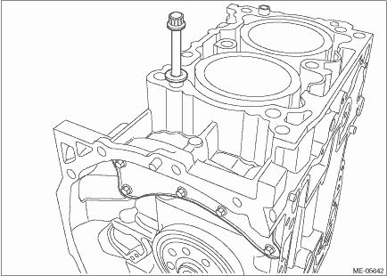
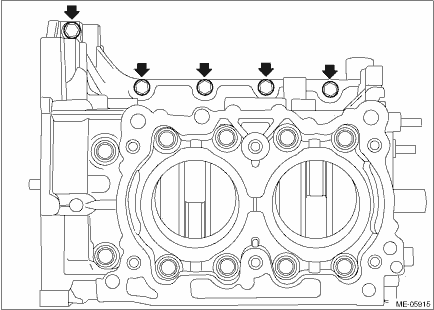
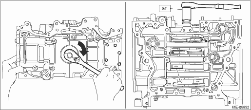
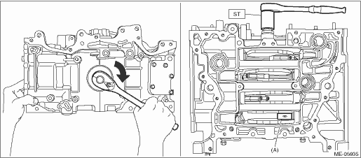
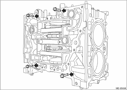
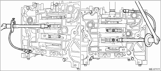
(2) Install the cylinder head bolt at the locations shown in the figure.
NOTE:
This procedure is required to tighten the cylinder block mounting bolts with specified angle using ST.
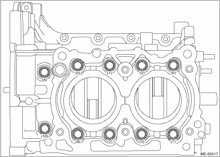
(3) Tighten all mounting bolts with a torque of 35 N·m (3.6 kgf-m, 25.8 ft-lb) in numerical order as shown in the figure.
CAUTION:
When tightening the mounting bolts with specified torque, hold the cylinder block LH while not holding the cylinder block RH to ensure the joint accuracy of the cylinder block.
(4) Loosen all mounting bolts by 180° in numerical order as shown in the figure.
CAUTION:
When loosening the mounting bolts, hold the cylinder block LH while not holding the cylinder block RH to ensure the joint accuracy of the cylinder block.

(5) Tighten all mounting bolts with a torque of 35 N·m (3.6 kgf-m, 25.8 ft-lb) in numerical order as shown in the figure.
CAUTION:
When tightening the mounting bolts with specified torque, hold the cylinder block LH while not holding the cylinder block RH to ensure the joint accuracy of the cylinder block.
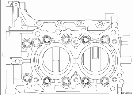
(6) Loosen the mounting bolts (4 places) by 180° in numerical order as shown in the figure.
CAUTION:
When loosening the mounting bolts, hold the cylinder block LH while not holding the cylinder block RH to ensure the joint accuracy of the cylinder block.

(7) Tighten the mounting bolts (4 places) with a torque of 17 N·m (1.7 kgf-m, 12.5 ft-lb) in numerical order as shown in the figure.
CAUTION:
When tightening the mounting bolts with specified torque, hold the cylinder block LH while not holding the cylinder block RH to ensure the joint accuracy of the cylinder block.
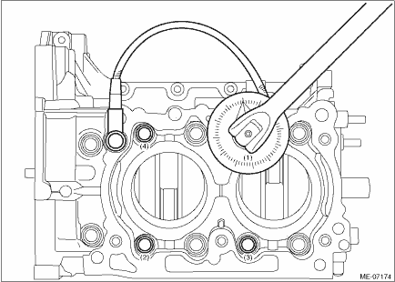
(8) Using angle gauge, tighten the mounting bolts (4 places) with specified angle in numerical order as shown in the figure.
CAUTION:
When tightening the mounting bolts with specified angle, hold the cylinder block LH while not holding the cylinder block RH to ensure the joint accuracy of the cylinder block.
Tightening angle:
60°±2°
(9) Loosen the mounting bolts (6 places) by 180° in numerical order as shown in the figure.
CAUTION:
When loosening the mounting bolts, hold the cylinder block LH while not holding the cylinder block RH to ensure the joint accuracy of the cylinder block.

(10) Tighten the mounting bolts (6 places) with a torque of 17 N·m (1.7 kgf-m, 12.5 ft-lb) in numerical order as shown in the figure.
CAUTION:
When tightening the mounting bolts with specified torque, hold the cylinder block LH while not holding the cylinder block RH to ensure the joint accuracy of the cylinder block.

(11) Using angle gauge, tighten the mounting bolts (6 places) with specified angle in numerical order as shown in the figure.
CAUTION:
When tightening the mounting bolts with specified angle, hold the cylinder block LH while not holding the cylinder block RH to ensure the joint accuracy of the cylinder block.
Tightening angle:
60°±2°
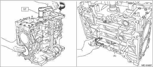
(12) Remove the cylinder head bolt attached at the locations shown in the figure.
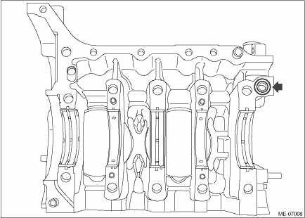
(13) Install the bolt shown in the figure.
NOTE:
After tightening, if the liquid gasket is squeezed out in the seal surface area of the chain cover and oil pan upper, completely remove any liquid gasket that is squeezed out. Any liquid gasket on the chamfer area, however, should not be removed.
Tightening torque:
25 N·m (2.5 kgf-m, 18.4 ft-lb)
7. Set the part so that the oil pan side of cylinder block is on the upper side.
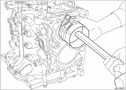
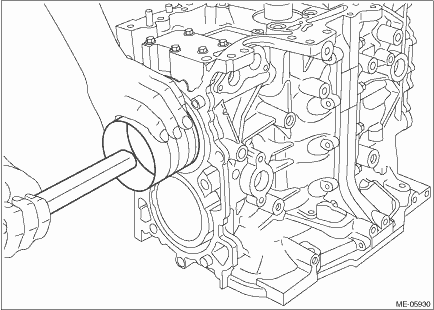
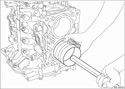
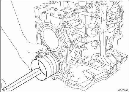
8. Apply a coat of engine oil to the oil seal inner periphery and outer periphery, and install the rear oil seal using ST1 and ST2.
NOTE:
Use a new rear oil seal.
| ST1 18671AA020 | OIL SEAL GUIDE |
| ST2 18657AA030 | OIL SEAL INSTALLER |
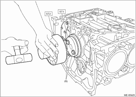
(A) | Rear oil seal | (B) | Drive plate or flywheel mounting bolt |
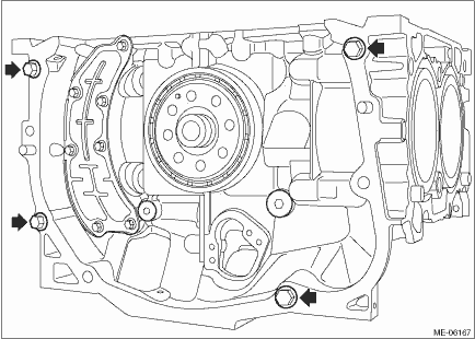
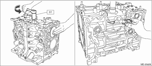
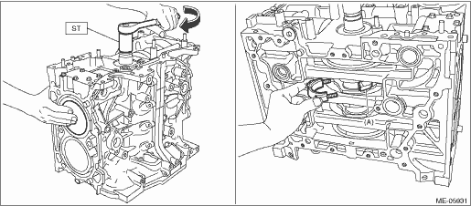
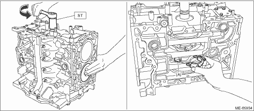
9. Install a bolt of suitable length (M10 ? P1.25) at the locations shown in the figure.
NOTE:
• This procedure is required to prevent the knock pin damage when the cylinder block is raised in the next step.
• Use the same length of bolt for the four bolts.
10. Raise the cylinder block so that the rear oil seal is on the lower side.
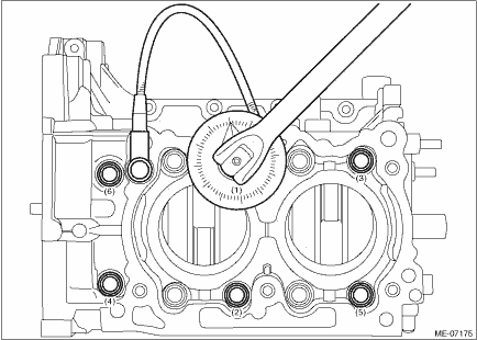
11. Adjust the positions of piston ring gap for each piston.
NOTE:
Check that the piston ring mark of compression ring faces the top side of the piston.
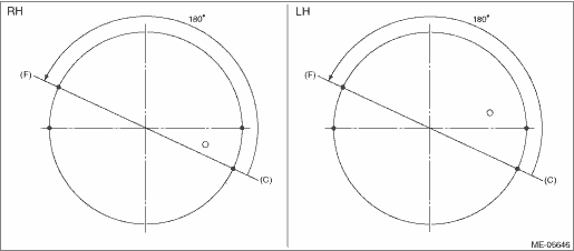
(1) Set the ring gap of the top ring to the position (A) in the figure.
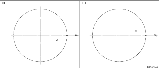
(2) Position the ring gap of second ring at (B) in the figure on the 180° opposite direction of (A).
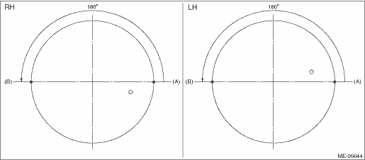
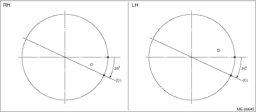
(3) Set the ring gap of the upper rail to the position (C) in the figure.
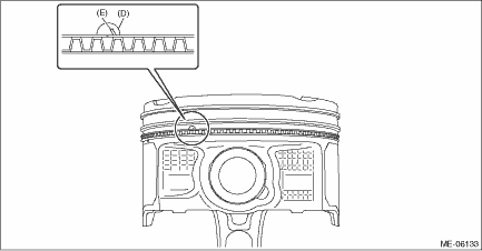
(4) Align the upper rail spin stopper (E) to the side hole (D) on the piston.
(5) Position the ring gap of expander at (F) in the figure on the 180° opposite direction of (C).
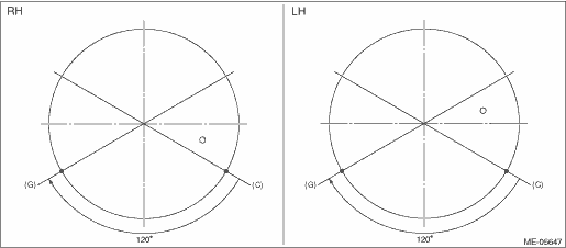
(6) Set the ring gap of lower rail at position (G), located 120° clockwise from (C) in the figure.
(7) Check that the positions of piston ring gap are properly adjusted.
NOTE:
When checking the positions of piston ring gap, also check that the piston ring gaps are not positioned within the range of piston skirt extended line.
12. Install the piston and connecting rod to the cylinder block.
(1) Apply engine oil to the outer circumference of each piston, crankshaft pin, and in the cylinder block.
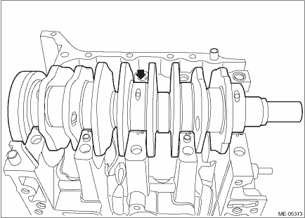
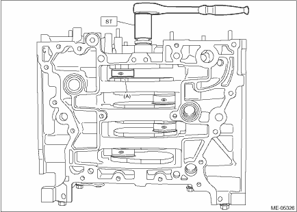
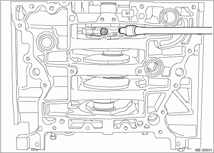
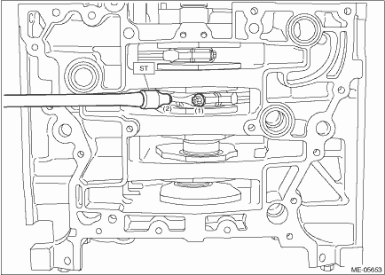
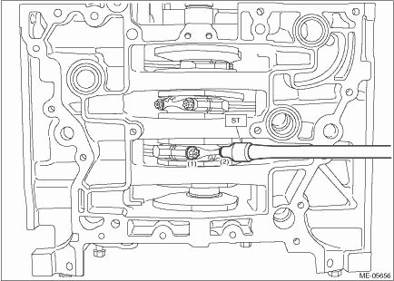
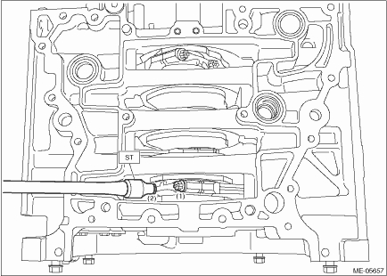
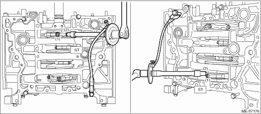
(2) Turn the crankshaft so that the #1 pin (A) of crankshaft is positioned at TDC using ST.
| ST 18252AA000 | CRANKSHAFT SOCKET |
(3) Compress the piston ring using piston ring compressor, and insert the #1 connecting rod with #1 piston into cylinder block.
CAUTION:
• Be careful not to damage the cylinder liner and #1 pin of crankshaft by the #1 connecting rod large end.
• Be careful not to apply strong impact when inserting to prevent connecting rod bearing from falling off.
NOTE:
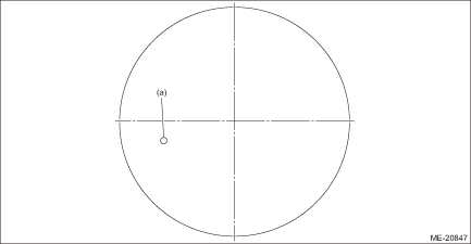
• Face the piston front mark (round mark) towards the front of the engine.
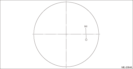
(a) | Front mark |
• Insert while lightly tapping the crown of the piston with the handle of a plastic hammer.
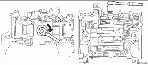
(4) Turn the crankshaft counterclockwise so that the #1 pin of crankshaft and the large end (A) of #1 connecting rod are positioned as shown in the figure using ST, while pressing the #1 piston crown, and then set the #1 connecting rod cap and #1 connecting rod cap bolt.
NOTE:
• Each connecting rod has its own mating cap. Make sure that they are assembled correctly by checking their matching symbol.
• Use a new connecting rod cap bolt.
• Apply a coat of engine oil to the #1 connecting rod cap seat and the connecting rod cap bolt threads.
| ST 18252AA000 | CRANKSHAFT SOCKET |
(5) Using ST, tighten the #1 connecting rod cap bolts to 10 N·m (1.0 kgf-m, 7.4 ft-lb) in numerical order as shown in the figure, then retighten the bolts to 22 N·m (2.2 kgf-m, 16.2 ft-lb) in numerical order as shown in the figure.
| ST 18270AA020 | SOCKET |
(6) Turn the crankshaft clockwise so that the #2 pin (A) of crankshaft is positioned at TDC using ST.
| ST 18252AA000 | CRANKSHAFT SOCKET |
(7) Compress the piston ring using piston ring compressor, and insert the #2 connecting rod with #2 piston into cylinder block.
CAUTION:
• Be careful not to damage the cylinder liner and #2 pin of crankshaft by the #2 connecting rod large end.
• Be careful not to apply strong impact when inserting to prevent connecting rod bearing from falling off.
NOTE:
• Face the piston front mark (round mark) towards the front of the engine.
(a) | Front mark |
• Insert while lightly tapping the crown of the piston with the handle of a plastic hammer.
(8) Turn the crankshaft clockwise so that the #2 pin of crankshaft and the large end (A) of #2 connecting rod are positioned as shown in the figure using ST, while pressing the #2 piston crown, and then set the #2 connecting rod cap and #2 connecting rod cap bolt.
NOTE:
• Each connecting rod has its own mating cap. Make sure that they are assembled correctly by checking their matching symbol.
• Use a new connecting rod cap bolt.
• Apply a coat of engine oil to the #2 connecting rod cap seat and the connecting rod cap bolt threads.
| ST 18252AA000 | CRANKSHAFT SOCKET |
(9) Using ST, tighten the #2 connecting rod cap bolts to 10 N·m (1.0 kgf-m, 7.4 ft-lb) in numerical order as shown in the figure, then retighten the bolts to 22 N·m (2.2 kgf-m, 16.2 ft-lb) in numerical order as shown in the figure.
| ST 18270AA020 | SOCKET |
(10) Turn the crankshaft clockwise so that the #3 pin (A) of crankshaft is positioned at TDC using ST.
| ST 18252AA000 | CRANKSHAFT SOCKET |
(11) Compress the piston ring using piston ring compressor, and insert the #3 connecting rod with #3 piston into cylinder block.
CAUTION:
• Be careful not to damage the cylinder liner and #3 pin of crankshaft by the #3 connecting rod large end.
• Be careful not to apply strong impact when inserting to prevent connecting rod bearing from falling off.
NOTE:
• Face the piston front mark (round mark) towards the front of the engine.
(a) | Front mark |
• Insert while lightly tapping the crown of the piston with the handle of a plastic hammer.
(12) Turn the crankshaft counterclockwise so that the #3 pin of crankshaft and the large end (A) of #3 connecting rod are positioned as shown in the figure using ST, while pressing the #3 piston crown, and then set the #3 connecting rod cap and #3 connecting rod cap bolt.
NOTE:
• Each connecting rod has its own mating cap. Make sure that they are assembled correctly by checking their matching symbol.
• Use a new connecting rod cap bolt.
• Apply a coat of engine oil to the #3 connecting rod cap seat and the connecting rod cap bolt threads.
| ST 18252AA000 | CRANKSHAFT SOCKET |
(13) Using ST, tighten the #3 connecting rod cap bolts to 10 N·m (1.0 kgf-m, 7.4 ft-lb) in numerical order as shown in the figure, then retighten the bolts to 22 N·m (2.2 kgf-m, 16.2 ft-lb) in numerical order as shown in the figure.
| ST 18270AA020 | SOCKET |
(14) Turn the crankshaft clockwise so that the #4 pin (A) of crankshaft is positioned at TDC using ST.
| ST 18252AA000 | CRANKSHAFT SOCKET |
(15) Compress the piston ring using piston ring compressor, and insert the #4 connecting rod with #4 piston into cylinder block.
CAUTION:
• Be careful not to damage the cylinder liner and #4 pin of crankshaft by the #4 connecting rod large end.
• Be careful not to apply strong impact when inserting to prevent connecting rod bearing from falling off.
NOTE:
• Face the piston front mark (round mark) towards the front of the engine.
(a) | Front mark |
• Insert while lightly tapping the crown of the piston with the handle of a plastic hammer.
(16) Turn the crankshaft clockwise so that the #4 pin of crankshaft and the large end (A) of #4 connecting rod are positioned as shown in the figure using ST, while pressing the #4 piston crown, and then set the #4 connecting rod cap and #4 connecting rod cap bolt.
NOTE:
• Each connecting rod has its own mating cap. Make sure that they are assembled correctly by checking their matching symbol.
• Use a new connecting rod cap bolt.
• Apply a coat of engine oil to the #4 connecting rod cap seat and the connecting rod cap bolt threads.
| ST 18252AA000 | CRANKSHAFT SOCKET |
(17) Using ST, tighten the #4 connecting rod cap bolts to 10 N·m (1.0 kgf-m, 7.4 ft-lb) in numerical order as shown in the figure, then retighten the bolts to 22 N·m (2.2 kgf-m, 16.2 ft-lb) in numerical order as shown in the figure.
| ST 18270AA020 | SOCKET |
(18) Install the cam carrier mounting bolts at the locations shown in the figure.
NOTE:
This procedure is required to tighten the connecting rod cap bolts with specified angle using ST.
(19) Turn the crankshaft so that the #1 connecting rod cap (A) and #4 connecting rod cap (B) is located at the position shown in the figure using ST.
| ST 18252AA000 | CRANKSHAFT SOCKET |
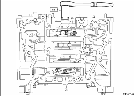
(20) Using ST and angle gauge, tighten the #1 connecting rod cap bolts and #4 connecting rod cap bolts with specified angle in numerical order as shown in the figure.
| ST 18270AA020 | SOCKET |
Tightening angle:
137°+3° −2°
(21) Turn the crankshaft so that the #2 connecting rod cap (A) and #3 connecting rod cap (B) is located at the position shown in the figure using ST.
| ST 18252AA000 | CRANKSHAFT SOCKET |
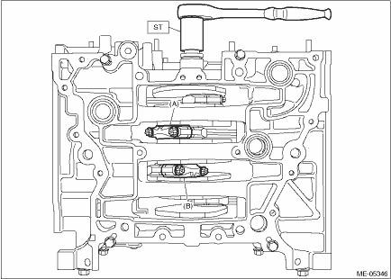
(22) Using ST and angle gauge, tighten the #2 connecting rod cap bolts and #3 connecting rod cap bolts with specified angle in numerical order as shown in the figure.
| ST 18270AA020 | SOCKET |
Tightening angle:
137°+3° −2°
(23) Remove the cam carrier mounting bolts attached at the locations shown in the figure.
13. Set the cylinder block so that the oil pan side faces upward, and remove the mounting bolts attached to the locations shown in the figure.
14. Install the oil pan upper. Oil Pan > INSTALLATION">
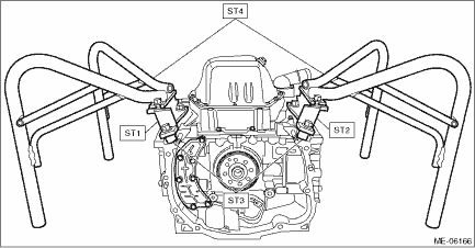
15. Install the ST1, ST2, ST3 and ST4 to the cylinder block and oil pan upper.
| ST1 498457000 | ENGINE STAND ADAPTER RH |
| ST2 498457100 | ENGINE STAND ADAPTER LH |
| ST3 18362AA020 | ADAPTER |
| ST4 499817100 | ENGINE STAND |
Tightening torque:
35 N·m (3.6 kgf-m, 25.8 ft-lb)
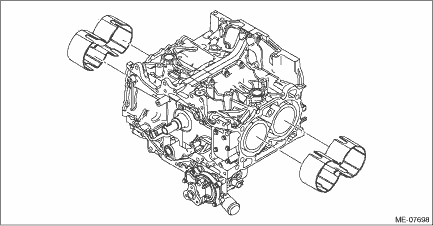
16. Install the water jacket spacer to the cylinder block RH and cylinder block LH.
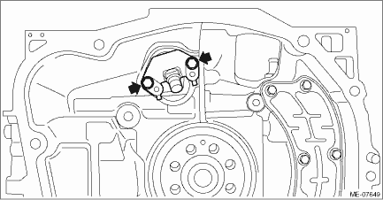
17. Install the crankshaft position sensor with crankshaft position sensor holder to the cylinder block LH.
Tightening torque:
6.4 N·m (0.7 kgf-m, 4.7 ft-lb)
18. Install the crankshaft position sensor plate with drive plate. (CVT model) Drive Plate > INSTALLATION">
19. Install the crankshaft position sensor plate with flywheel. (MT model) Flywheel > INSTALLATION">
20. Install the clutch disc and cover. (MT model) Clutch Disc and Cover > INSTALLATION">
21. Install the PCV valve. PCV Valve > INSTALLATION">
22. Install the knock sensor. Knock Sensor > INSTALLATION">
23. Install the O-ring to the cylinder block and PCV connector.
NOTE:
 Assembly
MECHANICAL(H4DO) > Cylinder BlockASSEMBLY1. CYLINDER BLOCK1. Apply liquid gasket to the threaded portion of the main gallery plug, and install the main gallery plug to the cylinder block LH.NOTE:Be ...
 Disassembly
MECHANICAL(H4DO) > Cylinder BlockDISASSEMBLY1. CYLINDER BLOCK1. Remove the oil separator cover from cylinder block RH.2. Remove the liquid gasket from cylinder block RH.3. Remove the cylinder block ...
Other materials:
Installation
EMISSION CONTROL (AUX. EMISSION CONTROL DEVICES)(H4DO) > EGR PipeINSTALLATION1. Temporarily install the EGR pipe to the intake manifold and water pipe assembly, and tighten the EGR pipe in numerical order as shown in the figure.NOTE:Use a new gasket.Tightening torque:6.4 N·m (0.7 kgf-m, 4. ...
Dtc b28a0 vehicle model judgment
EyeSight (DIAGNOSTICS) > Diagnostic Procedure with Diagnostic Trouble Code (DTC)DTC B28A0 VEHICLE MODEL JUDGMENTDetected when the model code for stereo camera and the model code used for CAN data are different.DTC DETECTING CONDITION:• Defective CAN system• Defective stereo camera&bul ...
Dtc u0422 invalid data received from body control module
CONTINUOUSLY VARIABLE TRANSMISSION (DIAGNOSTICS) > Diagnostic Procedure with Diagnostic Trouble Code (DTC)DTC U0422 INVALID DATA RECEIVED FROM BODY CONTROL MODULENOTE:Refer to “LAN SYSTEM (DIAGNOSTICS)” for diagnostic procedures. Basic Diagnostic Procedure">1. OUTLINE OF DIAG ...
