Subaru Crosstrek Service Manual: Assembly
MECHANICAL(H4DO) > Cylinder Block
ASSEMBLY
1. CYLINDER BLOCK
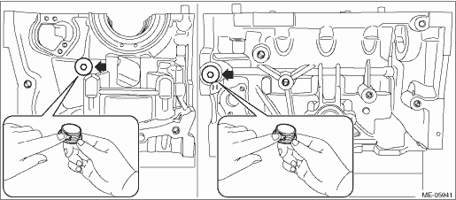
1. Apply liquid gasket to the threaded portion of the main gallery plug, and install the main gallery plug to the cylinder block LH.
NOTE:
Before applying liquid gasket, degrease the thread holes of the cylinder block LH and main gallery plug.
Liquid gasket:
THREE BOND 1105 (Part No. 004403010) or equivalent
Tightening torque:
37 N·m (3.8 kgf-m, 27.3 ft-lb)
2. Install the cylinder block plate onto cylinder block LH.
Tightening torque:
6.4 N·m (0.7 kgf-m, 4.7 ft-lb)
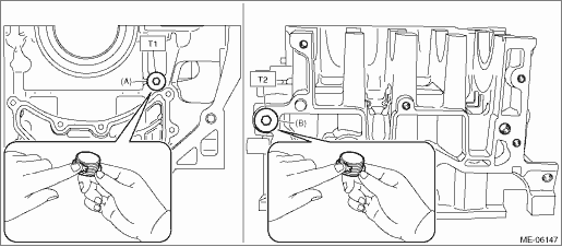
3. Apply liquid gasket to the threaded portions of cylinder block plug and main gallery plug, and install the cylinder block plug (A) and main gallery plug (B) to cylinder block RH.
NOTE:
Before applying liquid gasket, degrease the thread holes of the cylinder block RH, and the threaded portions of cylinder block plug and main gallery plug.
Liquid gasket:
THREE BOND 1105 (Part No. 004403010) or equivalent
Tightening torque:
T1: 16 N·m (1.6 kgf-m, 11.8 ft-lb)
T2: 37 N·m (3.8 kgf-m, 27.3 ft-lb)
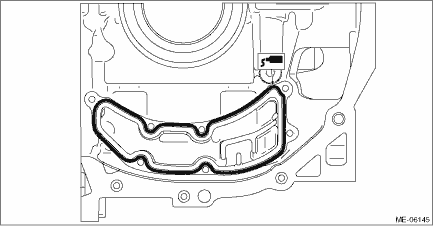
4. Install the oil separator cover to the cylinder block RH.
(1) Apply liquid gasket to the mating surfaces of oil separator cover.
NOTE:
• Use new oil separator cover.
• Before applying liquid gasket, degrease the old liquid gasket seal surface of cylinder block RH.
• Install within 5 min. after applying liquid gasket.
Liquid gasket:
Mating surface
THREE BOND 1217G (Part No. K0877Y0100), THREE BOND 1217H or equivalent
Liquid gasket applying diameter:
4±1 mm (0.1772±0.0197 in)
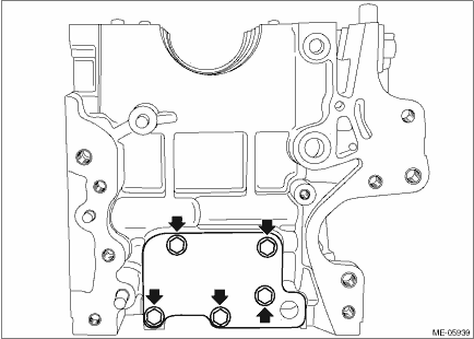
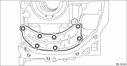
(2) Install the oil separator cover to the cylinder block RH, and tighten the oil separator cover bolts in numerical order as shown in the figure.
Tightening torque:
6.4 N·m (0.7 kgf-m, 4.7 ft-lb)
2. PISTON AND CONNECTING ROD
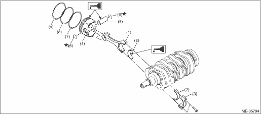
(1) | Connecting rod | (4) | Piston | (7) | Oil ring |
(2) | Connecting rod bearing | (5) | Piston pin | (8) | Second ring |
(3) | Connecting rod cap | (6) | Circlip | (9) | Top ring |
1. Install the connecting rod bearing to the connecting rod and connecting rod cap.
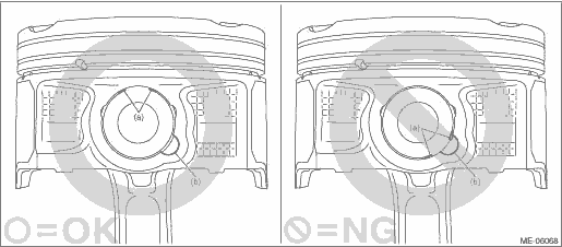
2. Install the circlip on one end of the piston using a flat tip screwdriver.
NOTE:
• Be careful not damage the piston, by wrapping the tip of flat tip screwdriver with tape.
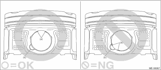
• Make sure the circlip is firmly inserted into the circlip groove.
• After installing the circlip, rotate the circlip so that its end part (a) and the cutout portion of circlip groove (b) do not match.
3. Set the piston to the connecting rod.
NOTE:
Align the front mark of piston and the connecting rod direction correctly as shown in the figure.
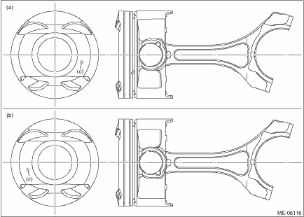
(a) | RH side (#1 and #3) | (b) | LH side (#2 and #4) | (c) | Front mark |
4. Apply engine oil to the piston pin, and attach the piston pin.
5. Install the circlip on the piston using a flat tip screwdriver.
NOTE:
• Be careful not damage the piston and piston pin, by wrapping the tip of flat tip screwdriver with tape.
• Make sure the circlip is firmly inserted into the circlip groove.
• After installing the circlip, rotate the circlip so that its end part (a) and the cutout portion of circlip groove (b) do not match.
6. Install the piston rings onto the piston.
(1) Install the oil rings in the order of expander, lower rail and upper rail by hand.
NOTE:
Oil ring consists of the upper rail, expander and lower rail.
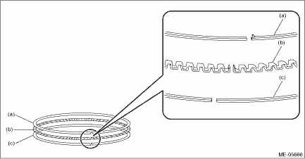
(a) | Upper rail | (b) | Expander | (c) | Lower rail |
(2) Install the compression rings in the order of second ring and top ring, using piston ring expander.
NOTE:
Install so that the compression ring mark faces the top side of the piston.
 Cylinder block
...
 Installation
MECHANICAL(H4DO) > Cylinder BlockINSTALLATION1. Apply engine oil to the crankshaft bearing, and install the crankshaft bearing to the cylinder block.CAUTION:• Place a wood board wrapped with ...
Other materials:
Making a call
There are several methods by which a call
can be made, as described below.
1. Press the HOME button on the audio
panel.
2. Touch the "PHONE" key.
3. Select the desired key to make a call
from the list.
Item
Function
Incoming
Calls
Display the history of inco ...
Dtc c1431 at
VEHICLE DYNAMICS CONTROL (VDC) (DIAGNOSTICS) > Diagnostic Procedure with Diagnostic Trouble Code (DTC)DTC C1431 ATDTC detecting condition:Defective TCMTrouble symptom:• ABS does not operate.• VDC does not operate.STEPCHECKYESNO1.CHECK TCM.1) Start the engine.2) Read the DTC of the TCM ...
Dtc u0416 invalid data received from vehicle dynamics control module
EyeSight (DIAGNOSTICS) > Diagnostic Procedure with Diagnostic Trouble Code (DTC)DTC U0416 INVALID DATA RECEIVED FROM VEHICLE DYNAMICS CONTROL MODULEFailure counter diagnosis of VDC control module (VDC CM)NOTE:Perform the diagnosis for LAN system. Basic Diagnostic Procedure > PROCEDURE"&g ...
