Subaru Crosstrek Service Manual: Installation
EMISSION CONTROL (AUX. EMISSION CONTROL DEVICES)(H4DO) > Leak Check Valve Assembly
INSTALLATION
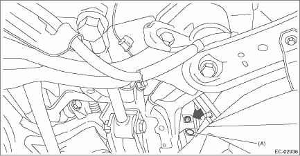
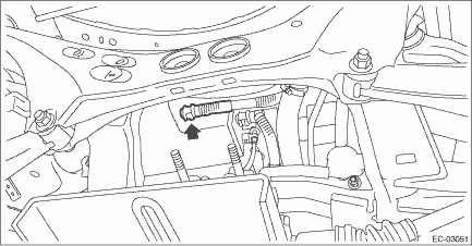
1. Install the leak check valve assembly to the vehicle with the bolt and clip (A).
Tightening torque:
7.5 N·m (0.8 kgf-m, 5.5 ft-lb)
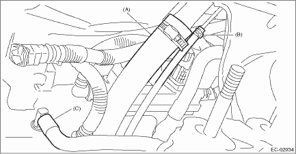
2. Connect the connector to the leak check valve assembly.
3. Connect the intake hose (C) to the connector.
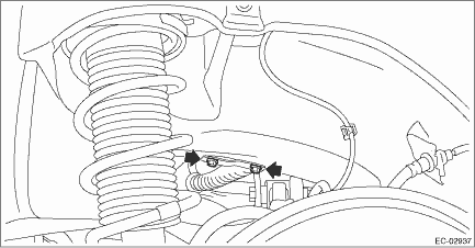
4. Securely insert the fuel filler hose (A) and evaporation hose (B) until the hose end contacts the spool, then attach the clamp and clip as shown in the figure.
Tightening torque:
2.5 N·m (0.3 kgf-m, 1.8 ft-lb)
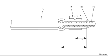
(1) | Hose | (3) | Spool | (4) | Pipe |
(2) | Clamp and clip |
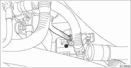
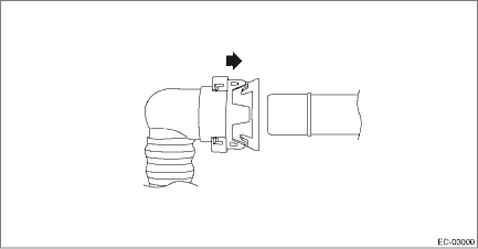
5. Connect the drain tube to the canister.
NOTE:
Connect the quick connector as shown in the figure.
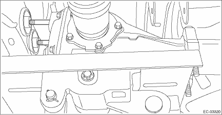
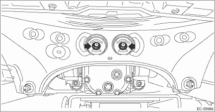
6. Lift up the transmission jack gradually, and set the rear differential to the rear sub frame assembly.
NOTE:
When inserting the stud bolt into the bushing portion of the rear sub frame assembly, adjust the angle and location of transmission jack and jack stand.
7. Temporarily tighten the self-locking nuts which hold the rear differential to the rear sub frame assembly.
NOTE:
Use a new self-locking nut.
8. Set the rear differential member to the rear sub frame assembly and rear differential, and temporarily tighten the self-lock nuts which secure the rear differential member to the rear sub frame assembly and rear differential.
NOTE:
Use a new self-locking nut.
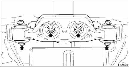
9. Remove the transmission jack from the rear differential.
10. Tighten the self-locking nuts which secure the rear differential member to the rear sub frame assembly and rear differential.
Tightening torque:
T1: 50 N·m (5.1 kgf-m, 36.9 ft-lb)
T2: 110 N·m (11.2 kgf-m, 81.1 ft-lb)
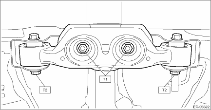
11. Tighten the self-locking nuts which secure the rear differential to the rear sub frame assembly.
Tightening torque:
70 N·m (7.1 kgf-m, 51.6 ft-lb)
12. Install the propeller shaft. Propeller Shaft > INSTALLATION">
13. Install the rear exhaust pipe. Rear Exhaust Pipe > INSTALLATION">
14. Lower the vehicle.
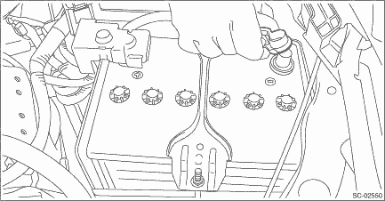
15. Connect the battery ground terminal.
 Inspection
EMISSION CONTROL (AUX. EMISSION CONTROL DEVICES)(H4DO) > Leak Check Valve AssemblyINSPECTION1. CHECK SWITCHING VALVE1. Check the resistance between switching valve terminals.Terminal No.Standard1 a ...
 Pcv hose
...
Other materials:
SRS airbag (Supplemental Restraint System airbag)
*SRS: This stands for supplemental restraint
system. This name is used because
the airbag system supplements the
vehicle's seatbelts.
Your vehicle is equipped with a supplemental
restraint system in addition to a
lap/shoulder belt at each front seating
position and each rear window-side sea ...
Dtc u0416 invalid data received from vehicle dynamics control module
POWER ASSISTED SYSTEM (POWER STEERING) (DIAGNOSTICS) > Diagnostic Procedure with Diagnostic Trouble Code (DTC)DTC U0416 INVALID DATA RECEIVED FROM VEHICLE DYNAMICS CONTROL MODULENOTE:Refer to “LAN SYSTEM” for diagnostic procedure. Basic Diagnostic Procedure"> ...
By outgoing calls
On the phone (menu) screen, select the
"Outgoing Calls" key to open the "Outgoing
Calls" screen. You can make a call
by selecting an item in the outgoing call
history list.
If there is no outgoing call history, a
message appears to indicate that there
is no outgoing call history data.
...
