Subaru Crosstrek Service Manual: Inspection
LIGHTING SYSTEM > Turn Signal Light & Hazard Light Unit
INSPECTION
1. Disconnect the connector of the turn signal & hazard unit.
2. Measure the voltage between the turn signal & hazard unit connector and the chassis ground.
Preparation tool:
Circuit tester
Terminal No. | Inspection conditions | Standard | Connection diagram |
4 (+) — Chassis ground (−) | Always | 10 — 14 V |
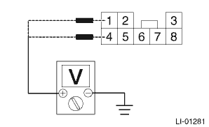
1 (+) — Chassis ground (−)
IG OFF > ON
Less than 1 V > 10 — 14 V
Repair or replace the harness if the inspection result is not within the standard value.
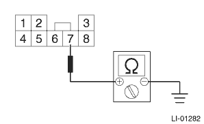
3. Measure the resistance between the turn signal & hazard unit connector and the chassis ground.
Terminal No. | Inspection conditions | Standard | Connection diagram |
7 — Chassis ground | Always | Less than 1 ? |
Repair or replace the harness if the inspection result is not within the standard value.
4. Connect the turn signal & hazard unit connector.
5. Measure the voltage between turn signal & hazard unit and chassis ground.
Terminal No. | Input/Output | Inspection conditions | Standard |
6 (+) — Chassis ground (−) | Input | Turn signal switch (right) OFF > ON | 9 V or more > less than 1 V |
5 (+) — Chassis ground (−) | Input | Turn signal switch (left) OFF > ON | 9 V or more > less than 1 V |
8 (+) — Chassis ground (−) | Input | Hazard switch OFF > ON | 9 V or more > less than 1 V |
2 (+) — Chassis ground (−) | Output | Turn signal switch (right) OFF > ON | Repeat less than 1 V > less than 1 V ←> more than 9 V at 60 to 120 times per minute. |
3 (+) — Chassis ground (−) | Output | Turn signal switch (left) OFF > ON | Repeat less than 1 V > less than 1 V ←> more than 9 V at 60 to 120 times per minute. |
2 (+) — Chassis ground (−) | Output | Hazard switch OFF > ON | Repeat less than 1 V > less than 1 V ←> more than 9 V at 60 to 120 times per minute. |
3 (+) — Chassis ground (−) | Output | Hazard switch OFF > ON | Repeat less than 1 V > less than 1 V ←> more than 9 V at 60 to 120 times per minute. |
Replace the turn signal & hazard unit if the inspection result is not within the standard value.

 Removal
LIGHTING SYSTEM > Turn Signal Light & Hazard Light UnitREMOVALCAUTION:Before handling the airbag system components, refer to “CAUTION” of “General Description” in &ldquo ...
Other materials:
Adjustment
CONTROL SYSTEMS > Select CableADJUSTMENT1. Shift the select lever to “N” range.2. Lift up the vehicle.3. Remove the center exhaust pipe. Center Exhaust Pipe > REMOVAL">4. Remove the center exhaust cover.5. Loosen the adjusting nuts on both sides.(A)Adjusting nut A(B)Adjust ...
Dtc p0391 camshaft position sensor "b" circuit range/performance bank 2
ENGINE (DIAGNOSTICS)(H4DO) > Diagnostic Procedure with Diagnostic Trouble Code (DTC)DTC P0391 CAMSHAFT POSITION SENSOR "B" CIRCUIT RANGE/PERFORMANCE BANK 2NOTE:For the diagnostic procedure, refer to DTC P0390. Diagnostic Procedure with Diagnostic Trouble Code (DTC) > DTC P0390 CAMSH ...
Removal
EXTERIOR/INTERIOR TRIM > Instrument Panel AssemblyREMOVALCAUTION:• Before handling the airbag system components, refer to “CAUTION” of “General Description” in “AIRBAG SYSTEM”. General Description > CAUTION">• Be careful not to damage th ...
