Subaru Crosstrek Service Manual: Installation
CONTROL SYSTEMS > Select Lever
INSTALLATION
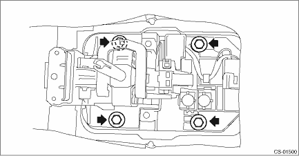
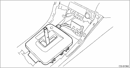
1. Set the select lever assembly to the vehicle body.
2. Tighten the four mounting bolts to attach the select lever assembly to the vehicle body.
Tightening torque:
18 N·m (1.8 kgf-m, 13.3 ft-lb)
3. Connect the harness connector.
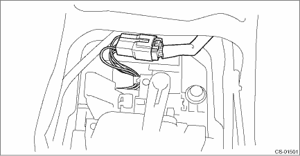
4. Install the harness clip to the select lever assembly.

5. Shift the select lever to “N” range.
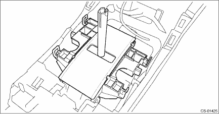
6. Install the indicator assembly, then connect the connector. (Model with boot shifter)
NOTE:
Insert the select lever through the blind hole sufficiently.
7. Install the panel center LWR LH and RH. Console Box > INSTALLATION">
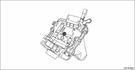
8. Install the blind A to the housing. (Model with gate shifter)
NOTE:
The blind A should be installed so that it is securely caught inside the tab of the housing.
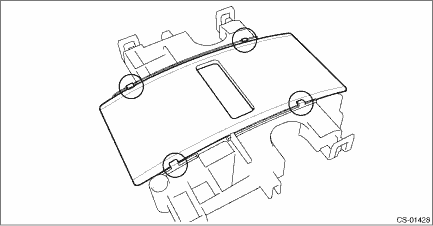
9. Install the blind B behind the blind A. (Model with gate shifter)
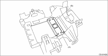
(A) | Blind B |
(B) | Blind A |
10. Install the housing. (Model with gate shifter)
11. Install the indicator cover, then connect the connector. (Model with gate shifter)
12. Install the cover shift lever. Console Box > INSTALLATION">
13. Accessing from the button side of the grip, attach the clamp grip pin.
14. Install the cover grip AT securely. (Model with gate shifter)
NOTE:
After installation, check that the cover grip AT cannot be detached.
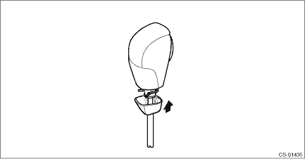
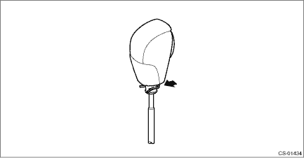
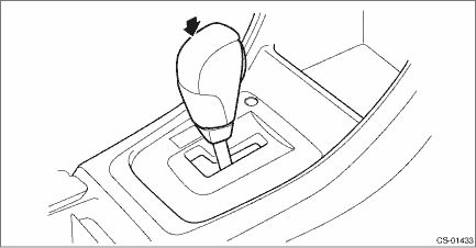
15. Insert the grip assembly to the select lever and press it down until a click is heard.
NOTE:
For model with boot shifter, insert the grip assembly while pressing the clamp grip pin with a finger in order to prevent it from popping out.
• Model with boot shifter
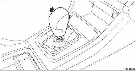
• Model with gate shifter
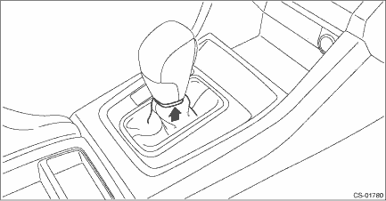
16. Securely install the boot assembly. (Model with boot shifter)
NOTE:
After installation, check that the boot assembly does not come off.
17. After installation of grip, check the following points.
• The grip will not come off.
• The button on the grip operates normally.
18. Install the console box. Console Box > INSTALLATION">
19. Shift the select lever to “N” range.
20. Lift up the vehicle.
21. Secure the cable to the bracket. Select Cable > INSTALLATION">
22. Adjust the select cable position. Select Cable > ADJUSTMENT">
23. After adjustment, confirm that the select lever operates properly at all range positions using the shift lock release button.
NOTE:
According to the select lever operation, confirm that the indicator positions are shown correctly.
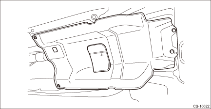
24. Install the center exhaust cover.
Tightening torque:
18 N·m (1.8 kgf-m, 13.3 ft-lb)
25. Install the center exhaust pipe. Center Exhaust Pipe > INSTALLATION">
26. Lower the vehicle.
27. Connect the battery ground terminal. NOTE">
28. Inspect the following items. If a malfunction is found in the inspection, adjust the select cable or inhibitor switch.
(1) The shift lock operates normally. AT Shift Lock Control System > INSPECTION">
(2) Engine starts when the select lever is in “P” or “N” range, but not in other ranges.
(3) Back-up light illuminates when the select lever is in the “R” range, but not in other ranges.
(4) Select lever and indicator positions are matched.
 Inspection
CONTROL SYSTEMS > Select LeverINSPECTION1. Inspect the removed parts by comparing with new parts for deformation, damage and wear. Repair or replace if defective.2. Inspect the select lever assembl ...
 Body integrated unit Note
CONTROL SYSTEMS > Body Integrated UnitNOTERefer to “Body Integrated Unit” for removal and installation procedure. Body Integrated Unit"> ...
Other materials:
How to change the source
The USB Audio playback screen can be
reached by the following methods:
Connect a USB memory. Refer to
"Connecting and disconnecting a USB
memory/portable device"
Select the "USB/iPod" key on the
source select screen. Refer to "Selecting
an audio source"
Select play mode
The play m ...
Removal
CONTINUOUSLY VARIABLE TRANSMISSION(TR580) > Secondary Pressure SensorREMOVALCAUTION:• Be sure to prevent water or oil from contacting the connector terminal of secondary pressure sensor. If adhesion occurs, replace with a new part.• When secondary pressure sensor is removed, CVTF leak ...
Specification
LUBRICATION(H4DO) > General DescriptionSPECIFICATIONLubrication methodForced lubricationOil pumpPump typeTrochoid typeNumber of teethInner rotor11Outer rotor12Outer rotor diameter ? Thicknessmm (in)77 ? 12 (3.03 ? 0.47)Performance(Oil temperature 120°C (248°F))600 r/minDisch ...
