Subaru Crosstrek Service Manual: Dtc b2a0a red led circuit
TELEMATICS SYSTEM (DIAGNOSTICS) > Diagnostic Procedure with Diagnostic Trouble Code (DTC)
DTC B2A0A RED LED CIRCUIT
Diagnosis start condition:
When ACC is ON.
DTC detecting condition:
• Current in LED is less than 1 mA. (Improper LED connection, etc.)
• Current is more than 200 mA for at least 50 ms. (Short-circuited LED, etc.)
Trouble symptom:
LED does not illuminate.
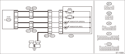
Wiring diagram:
NOTE:
For the coupling connector, refer to “WIRING SYSTEM”.
Telematics Telematics System > WIRING DIAGRAM">
CAUTION:
CommCheck is required after replacing the DCM. Telematics System > OPERATION">
| STEP | CHECK | YES | NO |
1.CHECK DTC.
Read the DTC. Diagnostic Code(s) Display">
Is DTC B2A0A displayed? (Current malfunction)
Diagnostic Procedure with Diagnostic Trouble Code (DTC) > DTC B2A0A RED LED CIRCUIT">Go to Step 2.
Even if DTC is displayed, the circuit has returned to a normal condition at this time. Reproduce the failure, and then perform the diagnosis again.
In this case, temporary poor contact of connector, temporary open or short circuit of harness may be the cause.
2.PERFORM THE SYSTEM OPERATION CHECK.
Perform [RED LED Lighting] in the system operation check mode. System Operation Check Mode">
Does the RED LED illuminate?
Even if DTC is displayed, the circuit has returned to a normal condition at this time. Reproduce the failure, and then perform the diagnosis again.
In this case, temporary poor contact of connector, temporary open or short circuit of harness may be the cause.
Diagnostic Procedure with Diagnostic Trouble Code (DTC) > DTC B2A0A RED LED CIRCUIT">Go to Step 3.
3.CHECK HARNESS (OPEN CIRCUIT).
1) Turn the ignition switch to OFF.
2) Disconnect the telematics button connector.
3) Disconnect the DCM connector.
4) Measure the resistance between telematics button connector and DCM connector.
Connector & terminal
(i270) No. 13 — (AD2) No. 7:
(AD2) No. 1 — Chassis ground:
Is the resistance 1 ? or less?
Diagnostic Procedure with Diagnostic Trouble Code (DTC) > DTC B2A0A RED LED CIRCUIT">Go to Step 4.
Repair or replace the open circuit of harness.
4.CHECK HARNESS (GROUND SHORT CIRCUIT).
Measure the resistance between DCM connector and chassis ground.
Connector & terminal
(i270) No. 13 — Chassis ground:
Is the resistance 1 M? or more?
Diagnostic Procedure with Diagnostic Trouble Code (DTC) > DTC B2A0A RED LED CIRCUIT">Go to Step 5.
Repair or replace the short circuit of the harness.
5.CHECK THE CONNECTOR (SHORT CIRCUIT TO POWER SUPPLY).
Measure the voltage between DCM connector and chassis ground.
Connector & terminal
(i270) No. 13 (+) — Chassis ground (−):
(AD2) No. 1 (+) — Chassis ground (−):
Is the voltage less than 1 V?
Diagnostic Procedure with Diagnostic Trouble Code (DTC) > DTC B2A0A RED LED CIRCUIT">Go to Step 6.
Repair or replace the short circuit of the harness.
6.CHECK THE TELEMATICS BUTTON (LED) UNIT.
Measure the resistance of the telematics button (LED) unit.
Terminals
No. 7 — No. 1:
Is there continuity?
Replace the DCM. Data Communication Module">
Replace the telematics button. Switches and Harness">
 Dtc b2a09 i-call button circuit
TELEMATICS SYSTEM (DIAGNOSTICS) > Diagnostic Procedure with Diagnostic Trouble Code (DTC)DTC B2A09 I-CALL BUTTON CIRCUITDiagnosis start condition:When ignition switch is ON.DTC detecting condition: ...
 Dtc b2a0b green led circuit
TELEMATICS SYSTEM (DIAGNOSTICS) > Diagnostic Procedure with Diagnostic Trouble Code (DTC)DTC B2A0B GREEN LED CIRCUITDiagnosis start condition:When ACC is ON.DTC detecting condition:• Current ...
Other materials:
Removal
AIRBAG SYSTEM > Side Airbag ModuleREMOVALCAUTION:Before handling the airbag system components, refer to “CAUTION” of “General Description” in “AIRBAG SYSTEM”. General Description > CAUTION">NOTE:Remove the passenger’s side by referring to driv ...
Removal
SECURITY AND LOCKS > IG Relay2 (Push Button Start)REMOVALCAUTION:Before handling the airbag system components, refer to “CAUTION” of “General Description” in “AIRBAG SYSTEM”. General Description > CAUTION">1. Disconnect the ground cable from battery ...
Dtc b1501 power supply system error detection
INSTRUMENTATION/DRIVER INFO (DIAGNOSTICS) > Diagnostic Procedure with Diagnostic Trouble Code (DTC)DTC B1501 POWER SUPPLY SYSTEM ERROR DETECTIONDTC detecting condition:Open or short in combination meter power supply circuitTrouble symptom:Defective operation of combination meterWiring diagram:Com ...
