Subaru Crosstrek Service Manual: Dtc b1501 power supply system error detection
INSTRUMENTATION/DRIVER INFO (DIAGNOSTICS) > Diagnostic Procedure with Diagnostic Trouble Code (DTC)
DTC B1501 POWER SUPPLY SYSTEM ERROR DETECTION
DTC detecting condition:
Open or short in combination meter power supply circuit
Trouble symptom:
Defective operation of combination meter
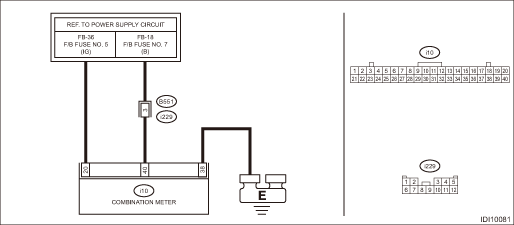
Wiring diagram:
Combination meter system Combination Meter System > WIRING DIAGRAM">
| STEP | CHECK | YES | NO |
1.CHECK POWER SUPPLY CIRCUIT.
Turn the ignition switch to ON, and confirm that the illumination of combination meter lights.
Does the illumination light?
Diagnostic Procedure with Diagnostic Trouble Code (DTC) > DTC B1501 POWER SUPPLY SYSTEM ERROR DETECTION">Go to Step 2.
Diagnostic Procedure with Diagnostic Trouble Code (DTC) > DTC B1501 POWER SUPPLY SYSTEM ERROR DETECTION">Go to Step 3.
2.CHECK DTC.
Read the DTC of the combination meter using the Subaru Select Monitor. Read Diagnostic Trouble Code (DTC)">
Is DTC B1501 a current malfunction?
Diagnostic Procedure with Diagnostic Trouble Code (DTC) > DTC B1501 POWER SUPPLY SYSTEM ERROR DETECTION">Go to Step 3.
Diagnostic Procedure with Diagnostic Trouble Code (DTC) > DTC B1501 POWER SUPPLY SYSTEM ERROR DETECTION">Go to Step 5.
3.CHECK FUSE.
1) Turn the ignition switch to OFF.
2) Check the fuse. Relay and Fuse">
Is the fuse OK?
Diagnostic Procedure with Diagnostic Trouble Code (DTC) > DTC B1501 POWER SUPPLY SYSTEM ERROR DETECTION">Go to Step 4.
Replace the defective fuse.
4.CHECK HARNESS.
1) Turn the ignition switch to OFF.
2) Disconnect the combination meter connector.
3) Using the tester, measure the voltage between terminals.
Connector & terminal
(i10) No. 20 (+) — Chassis ground (−):
(i10) No. 40 (+) — Chassis ground (−):
Is the voltage 8.5 — 16.5 V?
Diagnostic Procedure with Diagnostic Trouble Code (DTC) > DTC B1501 POWER SUPPLY SYSTEM ERROR DETECTION">Go to Step 5.
Repair the open circuit of harness or replace harness.
5.CHECK CONNECTOR.
1) Turn the ignition switch to OFF.
2) Disconnect connectors.
Is there poor contact of connector?
Repair or replace the poor contact of connector.
Even if DTC is displayed, the circuit has returned to a normal condition at this time. Reproduce the failure, and then perform the diagnosis again.
NOTE:
In this case, temporary poor contact of connector, temporary open or short circuit of harness may be the cause.
 Dtc b1507 external air temperature open/short-circuit detection
INSTRUMENTATION/DRIVER INFO (DIAGNOSTICS) > Diagnostic Procedure with Diagnostic Trouble Code (DTC)DTC B1507 EXTERNAL AIR TEMPERATURE OPEN/SHORT-CIRCUIT DETECTIONDTC detecting condition:Open or sho ...
 Dtc u0073 control module communication bus off
INSTRUMENTATION/DRIVER INFO (DIAGNOSTICS) > Diagnostic Procedure with Diagnostic Trouble Code (DTC)DTC U0073 CONTROL MODULE COMMUNICATION BUS OFFDetected when CAN line abnormality is detected.NOTE: ...
Other materials:
Removal
EXTERIOR/INTERIOR TRIM > Center ConsoleREMOVAL1. Remove the center grille assembly. Air Vent Grille > REMOVAL">2. Remove the audio assembly or navigation assembly. Audio > REMOVAL"> ...
Removal
FUEL INJECTION (FUEL SYSTEMS)(H4DO) > Camshaft Position SensorREMOVAL1. INTAKE SIDE1. Disconnect the ground cable from battery.2. Remove the air intake duct. (RH side only) Air Intake Duct > REMOVAL">3. Disconnect the connector (A) from the camshaft position sensor, and remove the cam ...
Disassembly
CONTROL SYSTEMS > Select LeverDISASSEMBLY1. GRIP ASSY1. Remove the button assembly_AT.(A)Claw2. Remove the rod COMPL.2. AT SELECT LEVER ASSEMBLY1. Remove the spacer plate.2. Remove the gasket.3. Insert a flat tip screwdriver with a thin tip under the connector and disconnect the harness connector ...
