Subaru Crosstrek Service Manual: Inspection
AUTO HEADLIGHT BEAM LEVELER SYSTEM (DIAGNOSTICS) > Subaru Select Monitor
INSPECTION
1. COMMUNICATION FOR INITIALIZING IMPOSSIBLE
Communication error with auto headlight beam leveler CM
Detecting condition:
• Defective harness connector
• Power supply circuit malfunction
• Defective auto headlight beam leveler CM
• Defective CAN communication circuit
• Defective Subaru Select Monitor
Trouble symptom:
Communication is impossible between auto headlight beam leveler CM and Subaru Select Monitor.
CAUTION:
Initialization is required after replacing the auto headlight beam leveler CM.
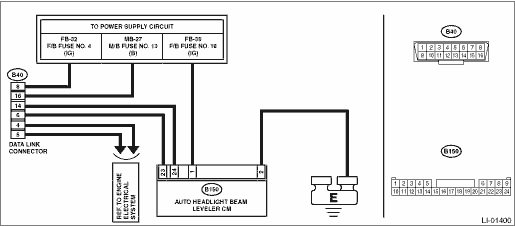
Wiring diagram:
Headlight beam leveler system Headlight Beam Leveler System > WIRING DIAGRAM">
| STEP | CHECK | YES | NO |
1.CHECK OTHER COMMUNICATION.
Communicate with the system other than the auto headlight beam leveler CM using the Subaru Select Monitor.
Is the communication to other control module possible?
Subaru Select Monitor > INSPECTION">Go to Step 2.
Perform the “Communication for Initializing Impossible” of LAN system. Subaru Select Monitor > COMMUNICATION FOR INITIALIZING IMPOSSIBLE">
2.CHECK LAN SYSTEM.
Inspect LAN system. Basic Diagnostic Procedure > PROCEDURE">
Is there any fault?
Perform the inspection according to the diagnosis for LAN system.
Subaru Select Monitor > INSPECTION">Go to Step 3.
3.CHECK FOR POOR CONTACT.
1) Turn the ignition switch to OFF.
2) Disconnect the auto headlight beam leveler CM connector.
3) Connect the disconnected connectors.
4) Communicate with the auto headlight beam leveler CM using the Subaru Select Monitor.
Is communication possible?
It is possible that temporary poor communication occurs.
Replace the auto headlight beam leveler CM. Auto Headlight Beam Leveler Control Module">

 Operation
AUTO HEADLIGHT BEAM LEVELER SYSTEM (DIAGNOSTICS) > Subaru Select MonitorOPERATION• For detailed operation procedures, refer to “Application help”.• If the auto headlight bea ...
Other materials:
Component
EMISSION CONTROL (AUX. EMISSION CONTROL DEVICES)(H4DO) > General DescriptionCOMPONENT1. CANISTER, LEAK CHECK VALVE ASSEMBLY AND DRAIN SEPARATORFor structures of the canister, leak check valve assembly and drain separator, refer to “FU (H4DO)”. General Description > COMPONENT" ...
Removal
EXTERIOR/INTERIOR TRIM > Roof TrimREMOVAL1. CROSSTREK MODELCAUTION:• Before handling the airbag system components, refer to “CAUTION” of “General Description” in “AIRBAG SYSTEM”. General Description > CAUTION">• Airbag system satellite s ...
Dtc p0300 random/multiple cylinder misfire detected
ENGINE (DIAGNOSTICS)(H4DO) > Diagnostic Procedure with Diagnostic Trouble Code (DTC)DTC P0300 RANDOM/MULTIPLE CYLINDER MISFIRE DETECTEDDTC DETECTING CONDITION:• Detected when two consecutive driving cycles with fault occur.• Immediately at fault recognition (A misfire which could dama ...
