Subaru Crosstrek Service Manual: Inspection
STARTING/CHARGING SYSTEMS(H4DO) > Starter
INSPECTION
NOTE:
• After the inspection, reinstall the disassembled or removed parts during the inspection in the reverse order of disassembly/removal procedure.
• Refer to component for tightening torque of each part. General Description > COMPONENT">
1. ARMATURE
1. Check the commutator for signs of seizure or stepped wear caused by roughness of the surface. If there is light wear, use sandpaper to repair.
2. Check for runout on the commutator. If excessive, replace the armature.
Commutator runout:
Standard
0.05 mm (0.0020 in)
Limit
0.10 mm (0.0039 in)

(A) | Dial gauge | (B) | V-block |
3. Check the depth of the segment mold. If it is not within the standard, replace the armature.
Depth of segment mold:
Standard
0.50 mm (0.020 in)
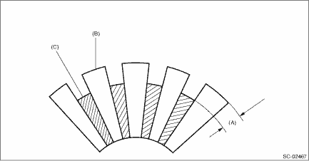
(A) | Depth of mold | (B) | Segment | (C) | Mold |
4. Place the armature on the growler tester to check for short circuits. While slowly turning the armature, support the steel sheet for the armature core. If the circuit of the armature is shorted, the steel sheet will vibrate, causing it to move towards the core. When the steel sheet has moved or vibrated, replace the armature.
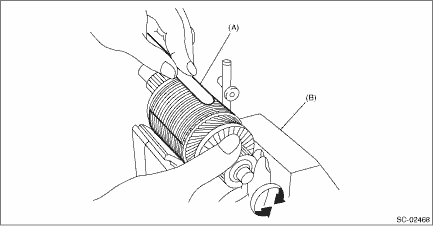
(A) | Steel sheet | (B) | Growler tester |
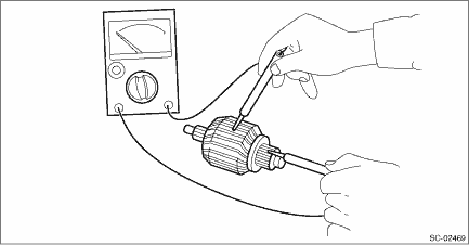
5. Use a circuit tester to touch the probe of one side to the commutator segment, and the other probe to the shaft. If there is continuity, replace the armature.
2. YOKE
Make sure that the pole is set at the predetermined position.
3. OVERRUNNING CLUTCH
Inspect the pinion, and if there is any wear or damage, replace the overrunning clutch. Also, check that the pinion rotates counterclockwise smoothly and does not rotate clockwise. If there is any fault, replace the overrunning clutch.
CAUTION:
To prevent spilling of grease, do not clean the overrunning clutch with oil.
4. BRUSH AND BRUSH HOLDER
1. Visually check the brush. If there is any abnormal wear or cracks, replace the brush.
2. Measure the length of the brush. If it exceeds service limits, replace the brush.
Brush length:
Standard
12.3 mm (0.484 in)
Limit
7.0 mm (0.276 in)
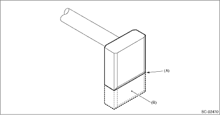
(A) | Service limit line | (B) | Brush |
3. Check that the brush moves smoothly in the brush holder.
4. Measure the brush spring force with a spring scale. Replace the brush holder if below the service limit.
Brush spring force:
Standard
15.9 — 19.5 N (1.62 — 1.99 kgf, 3.57 — 4.38 lbf) (when new)
Limit
2.5 N (0.25 kgf, 0.56 lbf)
5. SWITCH ASSEMBLY
Using a circuit tester, check there is continuity between S terminal and M terminal, and between S terminal and ground. Also, check that there is no continuity between M terminal and B terminal.
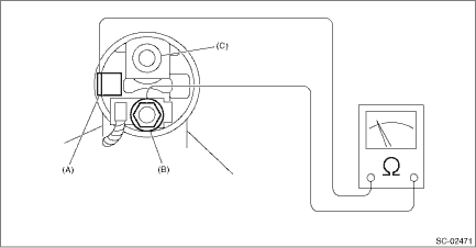
(A) | Terminal S | (B) | Terminal M | (C) | Terminal B |
Terminals | Standard |
Terminal S — terminal M | 1 ? or less |
Terminal S — Ground | 1 ? or less |
Terminal M — terminal B | 1 M? or more |
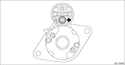
6. SWITCH ASSEMBLY OPERATION
CAUTION:
Perform the inspection in a short period of time. (Within 3 to 5 seconds)
1. Loosen the nut which holds the cable to the M terminal.
NOTE:
This procedure is required to facilitate the cable removal from the M terminal.
2. Connect the battery positive terminal to the switch assembly S terminal, and connect the battery negative terminal to the starter body. Then, if the pinion protrudes, it is normal.
NOTE:
The starter motor may rotate while the pinion protrudes. This occurs due to current that flows to the motor via pull-in coil. This is not a problem.
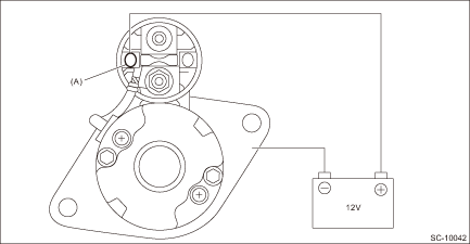
(A) | Terminal S |
3. Disconnect the cable from the M terminal. Check that the pinion is being protruded at this time.
CAUTION:
Hold the disconnected cable so that it does not contact the terminal or wiring.
4. Disconnect the battery negative terminal from the starter body. Then, if the pinion returns to its original position, it is normal.
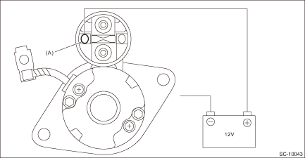
(A) | Terminal S |
7. NO-LOAD TEST
CAUTION:
• Use a thick cable due to large current flowing through the cable.
• It is recommended that the cross-section area of continuity part (shaded part) should be 20 mm2 (0.00310 sq in) or more for terminal B and ground, and 1.25 mm2 (0.00194 sq in) or more for terminal S.
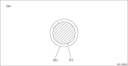
(a) | Cable cross-section | (b) | Cable shield part | (c) | Cable continuity part |
• It is possible to use a booster cable instead of wiring.
• Be careful not to burn yourself and cause a fire due to heat.
• Perform the no-load test in a short period of time. (Within 3 to 5 seconds)
NOTE:
For no-load test, use the circuit shown in figure.
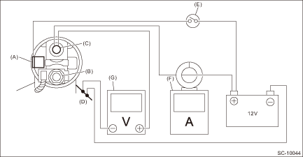
(A) | Terminal S | (B) | Terminal M | (C) | Terminal B |
(D) | Magnet switch | (E) | Switch | (F) | Circuit tester with clamp-type ammeter |
(G) | Circuit tester |
1. Using a vise, secure the starter.
CAUTION:
Be careful not to deform or damage the starter.
2. Turn the switch ON, and check that the pinion protrudes rapidly into the specified position and rotates powerfully without noise.
3. Check the current and voltage after its rotation speed stabilizes.
Current/Voltage
CVT model
90 A or less (approx. 11 V)
MT model
95 A or less (approx. 11 V)
8. OTHER INSPECTIONS
Check that the starter does not have deformation, cracks and any other damage.
 Disassembly
STARTING/CHARGING SYSTEMS(H4DO) > StarterDISASSEMBLYCAUTION:The starter should be placed through a no-load test whenever it has been overhauled.1. Disconnect the cable from the magnet switch assemb ...
 Installation
STARTING/CHARGING SYSTEMS(H4DO) > StarterINSTALLATIONInstall in the reverse order of removal.NOTE:• For CVT model, a nut is used at (a).• Tighten the starter and cable stay (b) together ...
Other materials:
Dtc c2022 tire 2 air pressure low (normal mode)
TIRE PRESSURE MONITORING SYSTEM (DIAGNOSTICS) > Diagnostic Procedure with Diagnostic Trouble Code (DTC)DTC C2022 TIRE 2 AIR PRESSURE LOW (NORMAL MODE)NOTE:Refer to DTC C2024 for diagnostic procedure. Diagnostic Procedure with Diagnostic Trouble Code (DTC) > DTC C2024 TIRE 4 AIR PRESSURE LOW ( ...
Inspection
INSTRUMENTATION/DRIVER INFO > Steering SwitchINSPECTION1. Measure the resistance between switch terminals.Preparation tool:Circuit testerTerminal No.Inspection conditionsStandard3 — 2 (UP)i/SET (DOWN)All OFFApprox. 1 M? or more (UP)ONLess than 1 ?i/SETONApprox. 1,000 ? (DOWN)ONApprox. 3,670 ?2. ...
SRS airbag (Supplemental Restraint System airbag)
*SRS: This stands for supplemental restraint
system. This name is used because
the airbag system supplements the
vehicle's seatbelts.
Your vehicle is equipped with a supplemental
restraint system in addition to a
lap/shoulder belt at each front seating
position and each rear window-side sea ...
