Subaru Crosstrek Service Manual: Disassembly
STARTING/CHARGING SYSTEMS(H4DO) > Starter
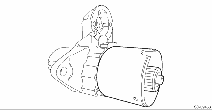
DISASSEMBLY
CAUTION:
The starter should be placed through a no-load test whenever it has been overhauled.
1. Disconnect the cable from the magnet switch assembly.
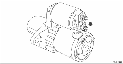
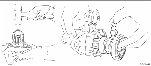
2. Remove the magnet switch assembly from the starter housing assembly.
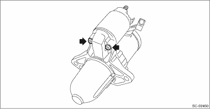
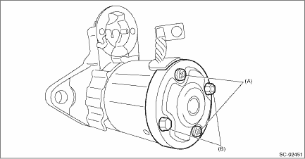
3. Remove screws (A) of the brush holder assembly, and through bolts (B) on both sides, and remove the starter cover assembly.
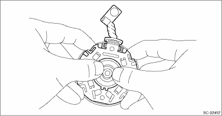
4. Remove the brush holder assembly from the armature assembly.
NOTE:
Hold the brush with your fingers so that the brush spring does not come flying out.
5. Remove the armature assembly and yoke assembly from the starter housing assembly together as a single unit.
6. Separate the armature assembly and yoke assembly.
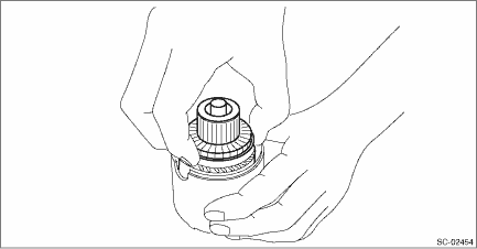
7. Remove the pinion gear from the internal gear assembly.
8. Remove seal rubber (A), plate (B), and seal rubber (C).
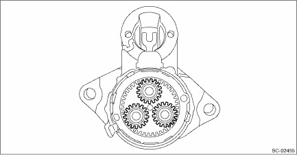
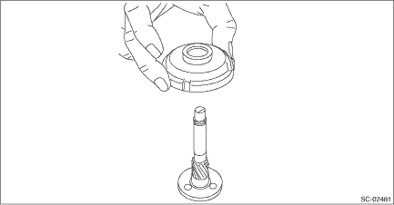
9. Lightly tap the starter housing assembly with a plastic hammer as shown in the figure, and remove the overrunning clutch, internal gear assembly, shaft and shift lever together as one unit.
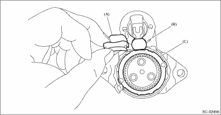
10. Use the following procedures to remove the overrunning clutch from the shaft.
(1) Use an appropriate tool (such as a fit socket wrench), and remove the stopper from snap ring by lightly tapping the stopper with a plastic hammer.
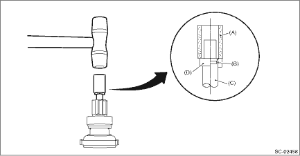
(A) | Appropriate tool | (B) | Snap ring | (C) | Shaft |
(D) | Stopper |
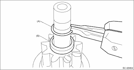
(2) Remove snap ring (A) from the shaft, and remove stopper (B).
(3) Remove the overrunning clutch from the shaft.
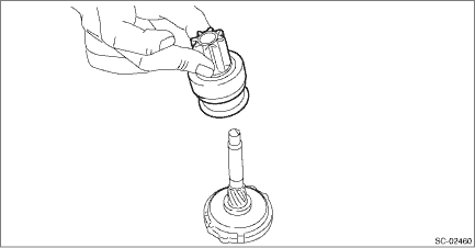
11. Separate the internal gear assembly and shaft.
 Removal
STARTING/CHARGING SYSTEMS(H4DO) > StarterREMOVAL1. Disconnect the ground cable from battery. NOTE">2. Remove the clip (A) from the air intake boot.3. Loosen the clamp (B) securing the air ...
 Inspection
STARTING/CHARGING SYSTEMS(H4DO) > StarterINSPECTIONNOTE:• After the inspection, reinstall the disassembled or removed parts during the inspection in the reverse order of disassembly/removal p ...
Other materials:
Dtc p0976 shift solenoid "b" control circuit low
CONTINUOUSLY VARIABLE TRANSMISSION (DIAGNOSTICS) > Diagnostic Procedure with Diagnostic Trouble Code (DTC)DTC P0976 SHIFT SOLENOID "B" CONTROL CIRCUIT LOWDTC detecting condition:Immediately at fault recognitionTrouble symptom:Gear is not changed. (No down-shift)CAUTION:Use the check boa ...
Assembly
CONTINUOUSLY VARIABLE TRANSMISSION(TR580) > Reduction Driven GearASSEMBLY1. Using the ST, attach the collar.NOTE:• Attach the collar in the correct direction.• Use a new reduction driven gear COMPL.ST 899580100INSTALLER2. Using the ST, install the parking gear.ST 499757002INSTAL ...
Component
SECURITY AND LOCKS > General DescriptionCOMPONENT1. DOOR LOCK ASSEMBLY(A)Front(B)Rear (1)Grommet - screw(9)Key lock - door (driver’s seat only)(17)Frame ASSY - rear door outer(2)Remote ASSY - door(10)Spacer - door handle outer B (3)Cap remote(11)Spacer - door handle outer ATightening ...
