Subaru Crosstrek Service Manual: Inspection
COMMUNICATION SYSTEM > Horn Switch
INSPECTION
1. CHECK HORN SWITCH
CAUTION:
Before handling the airbag system components, refer to “CAUTION” of “General Description” in “AIRBAG SYSTEM”. General Description > CAUTION">
1. Turn the ignition switch to OFF.
2. Disconnect the ground cable from battery and wait for at least 60 seconds before starting work. NOTE">
3. Remove the driver’s airbag module. Driver’s Airbag Module > REMOVAL">
4. Check that the connection of the horn switch harness connector is correct.
5. Disconnect the horn switch harness connector and check the resistance between the harness connectors.
Preparation tool:
Circuit tester
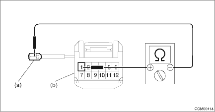
(a) | Ground terminal | (b) | Horn switch terminal |
Terminal No. | Inspection conditions | Standard |
Horn switch terminal — ground terminal | Always | Less than 1 ? |
6. Replace the driver’s airbag module if the inspection result is not within the standard value.
2. CHECK ROLL CONNECTOR
CAUTION:
• Before handling the airbag system components, refer to “CAUTION” of “General Description” in “AIRBAG SYSTEM”. General Description > CAUTION">
• If the steering wheel and steering angle sensor (steering roll connector) are removed, be sure to perform the following operations.
– Align the center position of the steering roll connector.
– Perform the neutral position setting of the steering angle sensor.
1. Turn the ignition switch to OFF.
2. Disconnect the ground cable from battery and wait for at least 60 seconds before starting work. NOTE">
3. Remove the roll connector. Roll Connector > REMOVAL">
4. Check the resistance between roll connector terminals.
Preparation tool:
Circuit tester
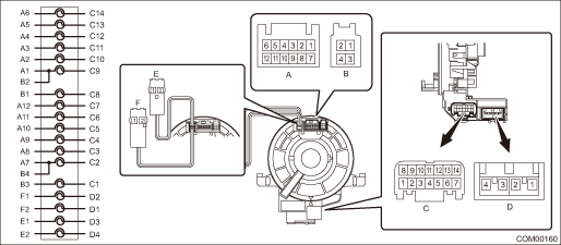
Terminal No. | Inspection conditions | Standard |
A1 — C9 | Always | Less than 1 ? |
5. Replace the roll connector if the inspection result is not within the standard value.
 Horn switch
...
 Note
Note
COMMUNICATION SYSTEM > Horn SwitchNOTEHorn switch is a unit with the driver’s airbag module. For operation procedures, refer to “Driver’s Airbag Module” in “AIRBAG SYS ...
Other materials:
Removal
ENTERTAINMENT > AudioREMOVALCAUTION:Before handling the airbag system components, refer to “CAUTION” of “General Description” in “AIRBAG SYSTEM”. General Description > CAUTION">1. Disconnect the ground cable from battery and wait for at least 60 sec ...
Dtc p0842 transmission fluid pressure sensor/switch "a" circuit low
CONTINUOUSLY VARIABLE TRANSMISSION (DIAGNOSTICS) > Diagnostic Procedure with Diagnostic Trouble Code (DTC)DTC P0842 TRANSMISSION FLUID PRESSURE SENSOR/SWITCH "A" CIRCUIT LOWDTC detecting condition:Immediately at fault recognitionTrouble symptom:Shift characteristics malfunctionCAUTION:U ...
Inspection
WIPER AND WASHER SYSTEMS > Washer Tank and MotorINSPECTION1. WASHER PUMPApply battery voltage to the connector terminal of the motor pump assembly - washer, and make sure that the motor operates.2. WASHER FLUID LEVEL SENSOR1. Check the connection status of washer fluid level sensor connector.2. D ...
