
Subaru Crosstrek Service Manual: Preparation tool
REAR SUSPENSION > General Description
PREPARATION TOOL
1. SPECIAL TOOL
ILLUSTRATION | TOOL NUMBER | DESCRIPTION | REMARKS |
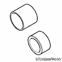
20099PA010
INSTALLER & REMOVER
• Used for replacing the bushing A - trailing link of the housing assembly - rear axle.
• Used together with BUSHING REMOVER (20099FG000).
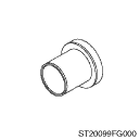
20099FG000
BUSHING REMOVER
• Used for replacing the bushing A - trailing link of the housing assembly - rear axle.
• Used together with base part of INSTALLER & REMOVER (20099PA000).
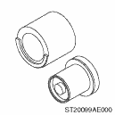
20099AE000
INSTALLER & REMOVER
Used for replacing the bushing B - lateral link.
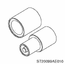
20099AE010
INSTALLER & REMOVER
Used for replacing the bushing C - lateral link.
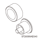
20099AE040
INSTALLER & REMOVER
Used for replacing the bushing C - lateral link.
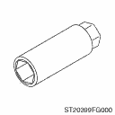
20399FG000
STRUT MOUNT SOCKET
• Used for removing and installing strut assembly and shock absorber assembly.
• Used for checking center nut torque of strut assembly and shock absorber assembly.
2. GENERAL TOOL
TOOL NAME | REMARKS |
Alignment tester | Used for measuring wheel alignment. |
Toe-in gauge | Used for toe-in measurement. |
Jack | Used for removing and installing suspension. |
Bearing puller | Used for removing bushings. |
Tie-rod ball joint puller | Used for disconnecting the lateral link assembly - front. |
Coil spring compressor | Used for disassembling and assembling shock absorber assembly. |
 Component
REAR SUSPENSION > General DescriptionCOMPONENT1. REAR SUSPENSION(1)Rear sub frame ASSY(11)Stopper LWRTightening torque: N·m (kgf-m, ft-lb)(2)Stopper UPR(12)Flange nutT1:30 (3.06, 22.1)(3)Sta ...

Other materials:
Maintenance schedule
U.S. models
For Subaru Ascent vehicles intended for the U.S. market, all required maintenance
procedures and service intervals are подробно outlined in the "Warranty and Maintenance
Booklet". To ensure proper care and long-term reliability of your Subaru Ascent,
always consu ...
Installation
BRAKE > Front Disc Brake AssemblyINSTALLATIONNOTE:Before installation, remove mud and foreign matter from the caliper body assembly and support - front disc brake.1. Check each part. Front Disc Brake Assembly > INSPECTION">2. Apply a thin coat of grease to the support - front disc bra ...
Dtc p0037 a/f / o2 heater control circuit low bank 1 sensor 2
ENGINE (DIAGNOSTICS)(H4DO) > Diagnostic Procedure with Diagnostic Trouble Code (DTC)DTC P0037 A/F / O2 HEATER CONTROL CIRCUIT LOW BANK 1 SENSOR 2DTC DETECTING CONDITION:Detected when two consecutive driving cycles with fault occur.CAUTION:After servicing or replacing faulty parts, perform Clear M ...
