Subaru Crosstrek Service Manual: Inspection
STARTING/CHARGING SYSTEMS(H4DO) > Generator
INSPECTION
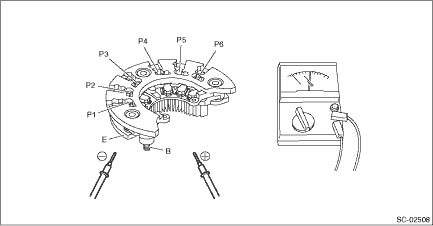
1. DIODE
CAUTION:
There is the possibility of damaging the diodes if a mega-tester (used to measure high voltages) or a similar measuring instrument is used. Never use a mega tester or equivalent for this test.
1. Check for continuity between the diode lead and terminal E or B. If continuity is not as shown in the table, replace the rectifier.
• At analog type tester
Tester lead | Continuity | |
−lead | +lead | |
E | P1, P2, P3, P4, P5, P6 | Yes |
B | No | |
P1, P2, P3, P4, P5, P6 | E | No |
B | Yes | |
• At digital type tester
Tester lead | Continuity | |
−lead | +lead | |
E | P1, P2, P3, P4, P5, P6 | No |
B | Yes | |
P1, P2, P3, P4, P5, P6 | E | Yes |
B | No | |
2. ROTOR
1. Slip ring surface
Inspect the slip rings for contamination or any roughness on the sliding surface. Repair the slip ring surface using a lathe or sand paper.
2. Slip ring outer diameter
Measure the slip ring outer diameter. Replace the rotor if the slip ring is worn.
Slip ring outer diameter:
Standard
22.7 mm (0.894 in)
Limit
22.1 mm (0.870 in)
3. Continuity test
Using a circuit tester, check the resistance between slip rings. If the resistance is not within the standard, replace the rotor.
Standard:
Approx. 2.0 — 2.4 ?

4. Insulation test
Check the continuity between slip ring and rotor core or shaft. If there is continuity, replace the rotor because the rotor coil is grounded.

5. Bearing
Check the bearings. If there is any noise, or the rotor does not rotate smoothly, replace the bearings.
3. STATOR COIL
1. Continuity test
Inspect the continuity between the stator coil terminals. If continuity is not as shown in the table, replace the stator coil.

(A) | Terminals |
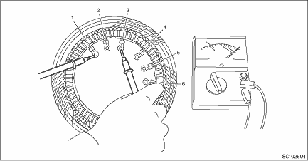
2. Insulation test
Inspect the continuity between the stator coil stator core and lead wire terminals. If there is continuity, replace the stator coil because the stator coil is grounded.

4. BRUSH
1. Measure the length of each brush. Replace the brush if wear exceeds service limits. There is a service limit mark (A) on each brush.
Brush length:
Standard (1)
22.5 mm (0.886 in)
Limit (2)
5.0 mm (0.197 in)

2. Check that there is appropriate pressure on the brush spring. Using a spring pressure indicator, push the brush into the brush holder until its tip protrudes 2 mm (0.0787 in). Then measure the pressure of brush spring. If the pressure is 1.7 N (173 gf, 6.11 ozf) or less, replace the brush spring. 4.1 — 5.3 N (418 — 540 gf, 14.75 — 19.06 ozf) pressure is required on the new spring.

5. BALL BEARING
Check the ball bearings. Replace the ball bearings if there is resistance in the rotation, or if there is any abnormal noise.
 Disassembly
STARTING/CHARGING SYSTEMS(H4DO) > GeneratorDISASSEMBLY1. Remove the cap from the generator.2. Remove four bolts.3. Use a drier to heat the rear cover (A) portion to 50 — 60°C (122 — ...
 Installation
STARTING/CHARGING SYSTEMS(H4DO) > GeneratorINSTALLATION1. Temporarily install the generator bracket to the engine and tighten the bolts in the numerical order.Tightening torque:36 N·m (3.7 k ...
Other materials:
Dtc b1760 occupant detection sensor mat
OCCUPANT DETECTION SYSTEM (DIAGNOSTICS) > Diagnostic Procedure with Diagnostic Trouble Code (DTC)DTC B1760 OCCUPANT DETECTION SENSOR MATDiagnosis start condition:Ignition voltage is 8 V to 16 V.DTC detecting condition:• Occupant detection sensor is faulty.• Occupant detection sensor c ...
Installation
FUEL INJECTION (FUEL SYSTEMS)(H4DO) > Fuel Level SensorINSTALLATIONInstall in the reverse order of removal.CAUTION:Be sure to install the fuel level sensor harness to the clip first, then install the connector cable. Otherwise, malfunction may occur.(A)Fuel level sensor harness(B)Connector cable ...
Caution
INSTRUMENTATION/DRIVER INFO > General DescriptionCAUTION• Before disassembling or reassembling parts, always disconnect the battery ground cable from battery. When replacing the audio, control module and other parts provided with memory functions, record the memory contents before disconnec ...
