Subaru Crosstrek Service Manual: Disassembly
STARTING/CHARGING SYSTEMS(H4DO) > Generator
DISASSEMBLY
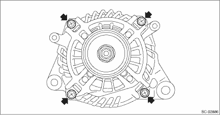
1. Remove the cap from the generator.

2. Remove four bolts.
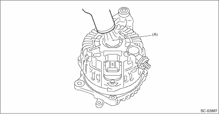
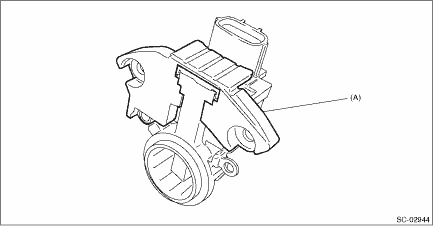
3. Use a drier to heat the rear cover (A) portion to 50 — 60°C (122 — 140°F).
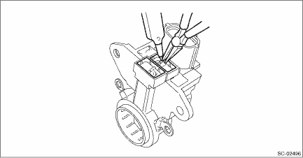
4. Insert a flat tip screwdriver or similar tool wrapped with protective tape into the gap between stator core and the front cover to disassemble.
(A) | Flat tip screwdriver |
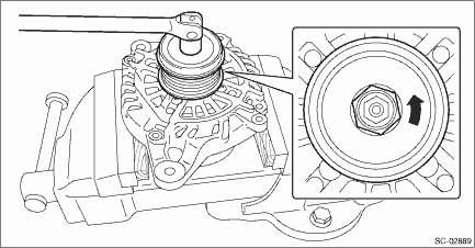
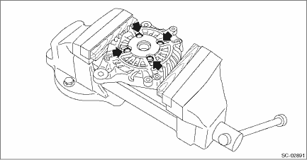
5. Hold the rotor on a vise and remove the pulley.
CAUTION:
When holding the rotor with a vise, place aluminum plates or wooden pieces on the vise jaws to prevent rotor from damage.
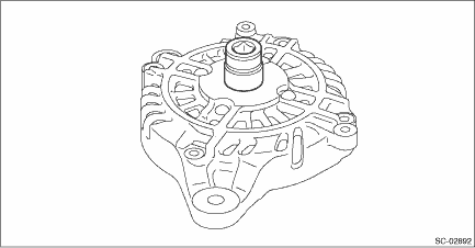
6. Remove the rotor from the front cover.
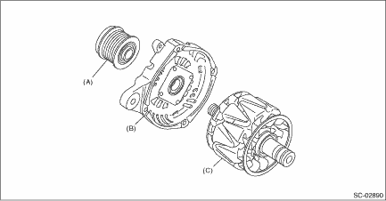
(A) | Pulley | (B) | Front cover | (C) | Rotor |
7. Use the following procedures to remove the ball bearings.
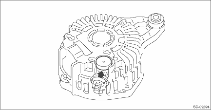
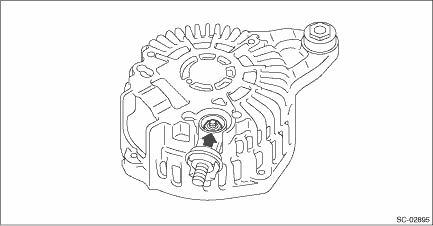
(1) Remove the bolt, and then detach the bearing retainer.
(2) Firmly attach an appropriate tool (such as a correct size socket wrench) to the bearing inner race.
(3) Use the press to push the ball bearings out from the front cover.
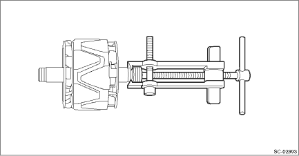
8. Using the bearing puller, remove the bearings from the rotor.
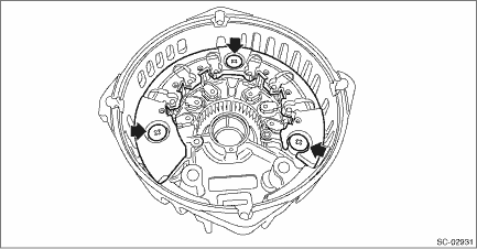
9. Remove six bolts which connect the rectifier and stator coil, then remove the stator coil.
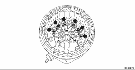
10. Remove four screws which secure the IC regulator to the rear cover, then remove the IC regulator.
11. Use the following procedures to remove the brush.
(1) Remove the cover A.
(A) | Cover A |
(2) Remove the cover B.
(A) | Cover B |
(3) Disconnect the connection and remove the brush.
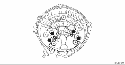
12. Remove the rectifier as follows.
(1) Remove the cover on terminal B.
(2) Remove the nut on terminal B.
(3) Remove the bolts which secure the rectifier, and remove the rectifier.
 Removal
STARTING/CHARGING SYSTEMS(H4DO) > GeneratorREMOVAL1. Remove the V-belt covers.2. Disconnect the ground cable from battery. NOTE">3. Remove the V-belts. V-belt > REMOVAL">4. Dis ...
 Inspection
STARTING/CHARGING SYSTEMS(H4DO) > GeneratorINSPECTION1. DIODECAUTION:There is the possibility of damaging the diodes if a mega-tester (used to measure high voltages) or a similar measuring instrume ...
Other materials:
Disassembly
CONTINUOUSLY VARIABLE TRANSMISSION(TR580) > Transmission CaseDISASSEMBLY1. Remove the oil stopper plate.2. Remove all plugs from the transmission case.3. Remove the oil seal using a screwdriver wrapped with cloth etc.4. Using the ST, remove the ball bearing of the secondary pulley.(1) Remove the ...
Dtc p0456 evap system (cpc) leak detected (very small leak)
ENGINE (DIAGNOSTICS)(H4DO) > Diagnostic Procedure with Diagnostic Trouble Code (DTC)DTC P0456 EVAP SYSTEM (CPC) LEAK DETECTED (VERY SMALL LEAK)NOTE:For the diagnostic procedure, refer to DTC P0455. Diagnostic Procedure with Diagnostic Trouble Code (DTC) > DTC P0455 EVAP SYSTEM (CPC) LEAK DETE ...
Turn signal lever
To activate the right turn signal, push the
turn signal lever up. To activate the left
turn signal, push the turn signal lever
down. When the turn is finished, the lever
will return automatically. If the lever does
not return after cornering, return the lever
to the neutral position by han ...
