Subaru Crosstrek Service Manual: Dtc p2103 throttle actuator "a" control motor circuit high
ENGINE (DIAGNOSTICS)(H4DO) > Diagnostic Procedure with Diagnostic Trouble Code (DTC)
DTC P2103 THROTTLE ACTUATOR "A" CONTROL MOTOR CIRCUIT HIGH
DTC DETECTING CONDITION:
Immediately at fault recognition
CAUTION:
After servicing or replacing faulty parts, perform Clear Memory Mode Clear Memory Mode > OPERATION"> , and Inspection Mode Inspection Mode > PROCEDURE">.
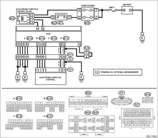
WIRING DIAGRAM:
Engine electrical system Engine Electrical System">
| STEP | CHECK | YES | NO |
1.CHECK ELECTRONIC THROTTLE CONTROL RELAY.
1) Turn the ignition switch to OFF.
2) Remove the electronic throttle control relay.
3) Measure the resistance between electronic throttle control relay terminals.
Terminals
No. 14 — No. 15:
Is the resistance 1 M? or more?
Diagnostic Procedure with Diagnostic Trouble Code (DTC) > DTC P2103 THROTTLE ACTUATOR "A" CONTROL MOTOR CIRCUIT HIGH">Go to Step 2.
Replace the electronic throttle control relay. Electronic Throttle Control Relay">
2.CHECK SHORT CIRCUIT OF ELECTRONIC THROTTLE CONTROL RELAY POWER SUPPLY.
1) Turn the ignition switch to ON.
2) Measure the voltage between electronic throttle control relay connector and chassis ground.
Connector & terminal
(B225) No. 14 (+) — Chassis ground (−):
Is the voltage 10 V or more?
Repair the short circuit to power in the harness between ECM connector and electronic throttle control relay connector.
Diagnostic Procedure with Diagnostic Trouble Code (DTC) > DTC P2103 THROTTLE ACTUATOR "A" CONTROL MOTOR CIRCUIT HIGH">Go to Step 3.
3.CHECK HARNESS BETWEEN ECM AND ELECTRONIC THROTTLE CONTROL RELAY CONNECTOR.
1) Turn the ignition switch to OFF.
2) Disconnect the connector from ECM.
3) Measure the resistance between ECM connector and chassis ground.
Connector & terminal
(B135) No. 17 — Chassis ground:
Is the resistance 1 M? or more?
Repair the poor contact of ECM connector.
Repair the short circuit to ground in harness between ECM connector and electronic throttle control relay connector.
1. OUTLINE OF DIAGNOSIS
Judge as NG when the electronic throttle control power is supplied even when ECM sets the electronic throttle control relay to OFF.
2. COMPONENT DESCRIPTION
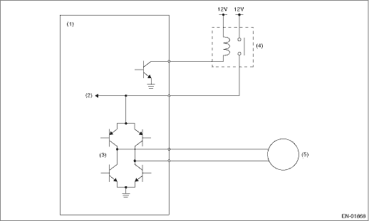
(1) | Engine control module (ECM) | (3) | Drive circuit | (5) | Motor |
(2) | Voltage detection circuit | (4) | Electronic throttle control relay |
3. EXECUTION CONDITION
Secondary Parameters | Execution condition |
Battery voltage | ≥ 6 V |
Electronic throttle control relay output | OFF |
4. GENERAL DRIVING CYCLE
• When ignition switch ON > OFF
• Ignition switch OFF > ON (Only after clearing memory)
5. DIAGNOSTIC METHOD
If the duration of time while the following conditions are met is longer than the time indicated, judge as NG.
Malfunction Criteria | Threshold Value |
Motor power voltage | ≥ 5 V |
Time Needed for Diagnosis: 600 ms
Malfunction Indicator Light Illumination: Illuminates as soon as a malfunction occurs.
 Dtc p2102 throttle actuator "a" control motor circuit low
ENGINE (DIAGNOSTICS)(H4DO) > Diagnostic Procedure with Diagnostic Trouble Code (DTC)DTC P2102 THROTTLE ACTUATOR "A" CONTROL MOTOR CIRCUIT LOWDTC DETECTING CONDITION:Immediately at fault r ...
 Dtc p2109 throttle/pedal position sensor "a" minimum stop performance
ENGINE (DIAGNOSTICS)(H4DO) > Diagnostic Procedure with Diagnostic Trouble Code (DTC)DTC P2109 THROTTLE/PEDAL POSITION SENSOR "A" MINIMUM STOP PERFORMANCENOTE:For the diagnostic procedure, ...
Other materials:
Select lever/gear position indicator
Upshift indicator
Downshift indicator
Select lever/gear position indicator
In the Subaru Ascent, this indicator provides clear visual feedback about the
current position of the select lever, helping the driver maintain full awareness
of the transmission state at all times.
When ma ...
Removal
INTAKE (INDUCTION)(H4DO) > Air Cleaner CaseREMOVAL1. Disconnect the ground cable from battery. NOTE">2. Remove the air intake duct. Air Intake Duct > REMOVAL">3. Disconnect the connector (A) from the mass air flow and intake air temperature sensor, and remove the clip (B).4. ...
Dtc b1013 ignition power
BODY CONTROL SYSTEM (DIAGNOSTICS) > Diagnostic Procedure with Diagnostic Trouble Code (DTC)DTC B1013 IGNITION POWERDTC detecting condition:Voltage failure caused by poor contact of IGN power supply circuitsTrouble symptom:Symptoms such as shift lock or wiper not operating may occur.Wiring diagram ...
