Subaru Crosstrek Service Manual: Dtc p2109 throttle/pedal position sensor "a" minimum stop performance
ENGINE (DIAGNOSTICS)(H4DO) > Diagnostic Procedure with Diagnostic Trouble Code (DTC)
DTC P2109 THROTTLE/PEDAL POSITION SENSOR "A" MINIMUM STOP PERFORMANCE
NOTE:
For the diagnostic procedure, refer to DTC P2101. Diagnostic Procedure with Diagnostic Trouble Code (DTC) > DTC P2101 THROTTLE ACTUATOR "A" CONTROL MOTOR CIRCUIT RANGE/PERFORMANCE">
1. OUTLINE OF DIAGNOSIS
Judge as NG when full close point learning cannot conducted or abnormal value is detected.
2. COMPONENT DESCRIPTION
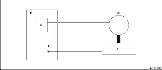
(1) | Engine control module (ECM) | (3) | Motor | (4) | Throttle position sensor |
(2) | Drive circuit |
3. EXECUTION CONDITION
Secondary parameters | Execution condition |
Minimum stop position | < −4.020% or > −4.020% |
| Throttle default position − Throttle minimum stop position | | < 1.162 ° |
4. GENERAL DRIVING CYCLE
Perform the diagnosis at full closed point learning.
5. DIAGNOSTIC METHOD
If the duration of time while the following conditions are met is longer than the time indicated, judge as NG.
Malfunction Criteria | Threshold Value |
12 V battery system voltage | < 6 V |
Time Needed for Diagnosis: 8 ms — 80 ms
Malfunction Indicator Light Illumination: Illuminates as soon as a malfunction occurs.
 Dtc p2103 throttle actuator "a" control motor circuit high
ENGINE (DIAGNOSTICS)(H4DO) > Diagnostic Procedure with Diagnostic Trouble Code (DTC)DTC P2103 THROTTLE ACTUATOR "A" CONTROL MOTOR CIRCUIT HIGHDTC DETECTING CONDITION:Immediately at fault ...
 Dtc p2119 throttle actuator "a" control throttle body range/performance
ENGINE (DIAGNOSTICS)(H4DO) > Diagnostic Procedure with Diagnostic Trouble Code (DTC)DTC P2119 THROTTLE ACTUATOR "A" CONTROL THROTTLE BODY RANGE/PERFORMANCENOTE:For the diagnostic procedur ...
Other materials:
Removal
FUEL INJECTION (FUEL SYSTEMS)(H4DO) > Fuel InjectorREMOVAL1. Release the fuel pressure. Fuel > PROCEDURE">2. Disconnect the ground cable from battery.3. Open the fuel filler lid and remove the fuel filler cap.NOTE:This operation is required to release the inner pressure of the fuel ta ...
Clear memory mode Operation
ENGINE (DIAGNOSTICS)(H4DO) > Clear Memory ModeOPERATION1. SUBARU SELECT MONITORNOTE:• Initial diagnosis of electronic throttle control is performed after memory clearance. Wait for 10 seconds or more after turning the ignition switch to ON, and then start the engine.• For detailed ope ...
Removal
MECHANICAL(H4DO) > Rocker CoverREMOVAL1. ROCKER COVER RHNOTE:When replacing a single part, perform the work with the engine assembly installed to body.1. When working on the vehicleNOTE:When working on the vehicle, perform the following steps also.(1) Remove the air cleaner case. Air Cleaner Cas ...
