Subaru Crosstrek Service Manual: Removal
FUEL INJECTION (FUEL SYSTEMS)(H4DO) > Fuel Injector
REMOVAL
1. Release the fuel pressure. Fuel > PROCEDURE">
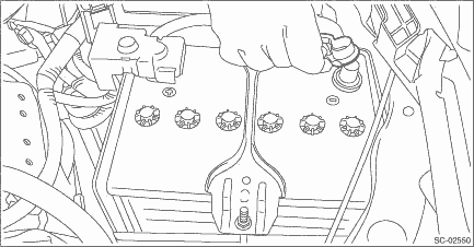
2. Disconnect the ground cable from battery.
3. Open the fuel filler lid and remove the fuel filler cap.
NOTE:
This operation is required to release the inner pressure of the fuel tank.
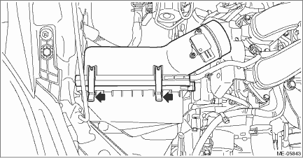
4. When removing the RH side, also perform the following steps.
(1) Remove the clip (A), and loosen the clamps (B) and (C) securing the air intake boot.
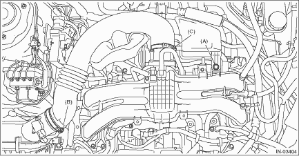
(2) Remove the air intake boot from the air cleaner case (rear) and throttle body, and move the air intake boot aside so that it does not interfere with the work.
(3) Disconnect the connector from the mass air flow and intake air temperature sensor, and remove the clip (A) securing the bulkhead wiring harness.
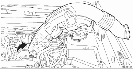
(4) Remove the air cleaner case (rear) together with the air cleaner element.
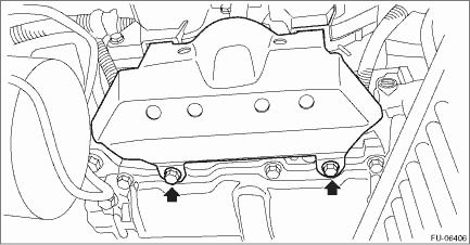
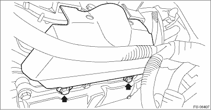
5. Remove the intake manifold protector.
• RH side
• LH side
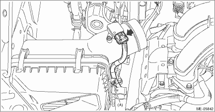
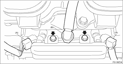
6. Disconnect the connectors (A) from fuel injector.
7. Disconnect the quick connector (B) of the fuel delivery pipe from the fuel pipe.
CAUTION:
• Be careful not to spill fuel.
• Catch the fuel from the pipes using a container or cloth.
NOTE:
Disconnect the quick connector as shown in the figure.
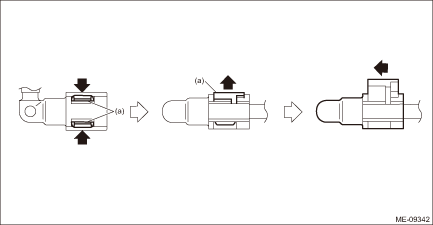
(a) | Slider |
8. Remove the bolts which hold fuel pipe onto the cam carrier, and remove the fuel pipe together with the fuel injector.
9. Remove the fuel injector from the fuel pipe.
(1) Remove the fuel injector holder from one side of flange section (A) of the fuel pipe.
(2) While holding one side of fuel injector holder (B) you removed in step (1) by finger, remove the other side of fuel injector holder from the flange section (C) of the fuel pipe.
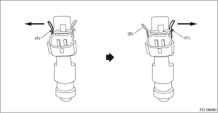
(3) Remove the fuel injector holder from the fuel pipe and fuel injector, and remove the fuel injector from the fuel pipe.
(4) Remove the fuel injector on the LH side in the same manner.
 Inspection
FUEL INJECTION (FUEL SYSTEMS)(H4DO) > Fuel InjectorINSPECTION1. Check that the fuel injector has no deformation, cracks or other damages.2. Measure the resistance between fuel injector terminals.Te ...
 Installation
FUEL INJECTION (FUEL SYSTEMS)(H4DO) > Fuel InjectorINSTALLATIONInstall in the reverse order of removal.NOTE:• Use new fuel injector holder, O-rings, rubbers and seal rings.• Install the ...
Other materials:
Specification
TELEMATICS SYSTEM (DIAGNOSTICS) > Control Module I/O SignalSPECIFICATION1. DATA COMMUNICATION MODULE (DCM)Terminal No.ContentMeasuring conditionStandardA1 — — — A2 — — — A3LED GREEN — — A4 ←> Chassis groundi-buttoni-button OFF > ON1.6 k? or more > less than 1 ?A ...
Dtc b1833 short in curtain shield airbag rh squib circuit (to +b)
AIRBAG SYSTEM (DIAGNOSTICS) > Diagnostic Chart with Trouble CodeDTC B1833 SHORT IN CURTAIN SHIELD AIRBAG RH SQUIB CIRCUIT (TO +B)Diagnosis start condition:Ignition voltage is 10 V to 16 V.DTC detecting condition:• Curtain airbag harness (RH) is shorted to power supply.• Curtain airbag ...
Inspection
WIPER AND WASHER SYSTEMS > Front Washer Nozzle and HoseINSPECTION• Make sure the nozzle - windshield washer and the hose - windshield washer are not clogged.• Make sure the hose - windshield washer is not bent.• Check the position of the nozzle - windshield washer. Front Washer ...
