Subaru Crosstrek Service Manual: Dtc p0366 camshaft position sensor "b" circuit range/performance bank 1
ENGINE (DIAGNOSTICS)(H4DO) > Diagnostic Procedure with Diagnostic Trouble Code (DTC)
DTC P0366 CAMSHAFT POSITION SENSOR "B" CIRCUIT RANGE/PERFORMANCE BANK 1
NOTE:
For the diagnostic procedure, refer to DTC P0365. Diagnostic Procedure with Diagnostic Trouble Code (DTC) > DTC P0365 CAMSHAFT POSITION SENSOR "B" CIRCUIT BANK 1">
1. OUTLINE OF DIAGNOSIS
Detect the malfunction of camshaft position sensor property.
Judge as NG when the number of camshaft signals remains abnormal.
2. COMPONENT DESCRIPTION
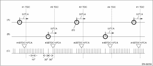
(A) | Camshaft signal (RH) | (B) | Camshaft signal (LH) | (C) | Crankshaft signal |
(D) | Camshaft position signal: When normal, there will be 2 camshaft position signals for every 2 crankshaft revolutions. |
3. EXECUTION CONDITION
Secondary Parameters | Execution condition |
Battery voltage | ≥ 10.9 V |
Elapsed time after starting the engine | ≥ 200 ms |
4. GENERAL DRIVING CYCLE
Always perform the diagnosis continuously.
5. DIAGNOSTIC METHOD
Judge as NG when the status where the number of camshaft position sensor signal in two crankshaft revolutions is other than 2 time(s).
Malfunction Criteria | Threshold Value |
Amount of camshaft sensor signal during 2 revs of crankshaft | ≠ 2 time(s) |
Time Needed for Diagnosis: Two engine revs. ? 4 time(s)
Malfunction Indicator Light Illumination: Illuminates as soon as a malfunction occurs.
 Dtc p0365 camshaft position sensor "b" circuit bank 1
ENGINE (DIAGNOSTICS)(H4DO) > Diagnostic Procedure with Diagnostic Trouble Code (DTC)DTC P0365 CAMSHAFT POSITION SENSOR "B" CIRCUIT BANK 1DTC DETECTING CONDITION:Immediately at fault recog ...
 Dtc p0390 camshaft position sensor "b" circuit bank 2
ENGINE (DIAGNOSTICS)(H4DO) > Diagnostic Procedure with Diagnostic Trouble Code (DTC)DTC P0390 CAMSHAFT POSITION SENSOR "B" CIRCUIT BANK 2DTC DETECTING CONDITION:Immediately at fault recog ...
Other materials:
Installation
EXTERIOR/INTERIOR TRIM > Instrument Panel AssemblyINSTALLATIONCAUTION:• Before handling the airbag system components, refer to “CAUTION” of “General Description” in “AIRBAG SYSTEM”. General Description > CAUTION">• After installing the p ...
Assembly
CONTINUOUSLY VARIABLE TRANSMISSION(TR580) > Converter CaseASSEMBLY1. Install the oil drain plug.Tightening torque:70 N·m (7.1 kgf-m, 51.6 ft-lb)2. Install the overflow drain plug.NOTE:Overflow plug of differential gear oil is temporarily attached.3. Install all plugs.NOTE:Use new O-rings.T ...
Dtc c1732 lateral g sensor
VEHICLE DYNAMICS CONTROL (VDC) (DIAGNOSTICS) > Diagnostic Procedure with Diagnostic Trouble Code (DTC)DTC C1732 LATERAL G SENSORDTC detecting condition:Defective lateral G sensorTrouble symptom:• ABS does not operate.• VDC does not operate.• Hill start assist does not operate.ST ...
