Subaru Crosstrek Service Manual: Dtc p0365 camshaft position sensor "b" circuit bank 1
ENGINE (DIAGNOSTICS)(H4DO) > Diagnostic Procedure with Diagnostic Trouble Code (DTC)
DTC P0365 CAMSHAFT POSITION SENSOR "B" CIRCUIT BANK 1
DTC DETECTING CONDITION:
Immediately at fault recognition
TROUBLE SYMPTOM:
• Engine stall
• Failure of engine to start
CAUTION:
After servicing or replacing faulty parts, perform Clear Memory Mode Clear Memory Mode > OPERATION"> , and Inspection Mode Inspection Mode > PROCEDURE">.
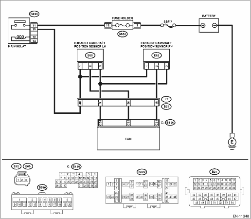
WIRING DIAGRAM:
Engine electrical system Engine Electrical System">
| STEP | CHECK | YES | NO |
1.CHECK POWER SUPPLY OF CAMSHAFT POSITION SENSOR.
1) Turn the ignition switch to OFF.
2) Disconnect the connector from camshaft position sensor.
3) Turn the ignition switch to ON.
4) Measure the voltage between camshaft position sensor connector and engine ground.
Connector & terminal
(E62) No. 1 (+) — Engine ground (−):
Is the voltage 10 V or more?
Diagnostic Procedure with Diagnostic Trouble Code (DTC) > DTC P0365 CAMSHAFT POSITION SENSOR "B" CIRCUIT BANK 1">Go to Step 2.
Repair the harness and connector.
NOTE:
In this case, repair the following item:
• Open circuit or short circuit to ground in harness between main relay connector and camshaft position sensor connector
• Poor contact of coupling connector
2.CHECK HARNESS BETWEEN ECM AND CAMSHAFT POSITION SENSOR CONNECTOR.
1) Turn the ignition switch to OFF.
2) Disconnect the connector from ECM.
3) Measure the resistance between ECM connector and camshaft position sensor connector.
Connector & terminal
(B136) No. 14 — (E62) No. 2:
(B136) No. 34 — (E62) No. 3:
Is the resistance less than 1 ??
Diagnostic Procedure with Diagnostic Trouble Code (DTC) > DTC P0365 CAMSHAFT POSITION SENSOR "B" CIRCUIT BANK 1">Go to Step 3.
Repair the harness and connector.
NOTE:
In this case, repair the following item:
• Open circuit in harness between ECM connector and camshaft position sensor connector
• Poor contact of coupling connector
3.CHECK HARNESS BETWEEN ECM AND CAMSHAFT POSITION SENSOR CONNECTOR.
Measure the resistance between camshaft position sensor connector and engine ground.
Connector & terminal
(E62) No. 2 — Engine ground:
Is the resistance 1 M? or more?
Diagnostic Procedure with Diagnostic Trouble Code (DTC) > DTC P0365 CAMSHAFT POSITION SENSOR "B" CIRCUIT BANK 1">Go to Step 4.
Repair short circuit to ground in harness between ECM connector and camshaft position sensor connector.
4.CHECK HARNESS BETWEEN ECM AND CAMSHAFT POSITION SENSOR CONNECTOR.
Measure the voltage between camshaft position sensor connector and engine ground.
Connector & terminal
(E62) No. 2 (+) — Engine ground (−):
Is the voltage 5 V or more?
Repair the short circuit to power in the harness between ECM connector and camshaft position sensor connector.
Diagnostic Procedure with Diagnostic Trouble Code (DTC) > DTC P0365 CAMSHAFT POSITION SENSOR "B" CIRCUIT BANK 1">Go to Step 5.
5.CHECK CONDITION OF CAMSHAFT POSITION SENSOR.
Is the camshaft position sensor installation bolt tightened securely?
Diagnostic Procedure with Diagnostic Trouble Code (DTC) > DTC P0365 CAMSHAFT POSITION SENSOR "B" CIRCUIT BANK 1">Go to Step 6.
Tighten the camshaft position sensor installation bolt securely.
6.CHECK CAMSHAFT POSITION SENSOR.
Check the waveform of the camshaft position sensor. Engine Control Module (ECM) I/O Signal">
Is there any abnormality in waveform?
Replace the camshaft position sensor. Camshaft Position Sensor">
Repair the following item.
• Poor contact of ECM connector
• Poor contact of camshaft position sensor connector
• Poor contact of coupling connector
1. OUTLINE OF DIAGNOSIS
Detect the open or short circuit of the camshaft position sensor.
When there is no camshaft position signal input continuously, judge as NG.
2. COMPONENT DESCRIPTION
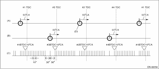
(A) | Camshaft signal (RH) | (B) | Camshaft signal (LH) | (C) | Crankshaft signal |
(D) | Camshaft position signal: When normal, there will be 2 camshaft position signals for every 2 crankshaft revolutions. |
3. EXECUTION CONDITION
Secondary Parameters | Execution condition |
Battery voltage | ≥ 10.9 V |
Elapsed time after starting the engine | ≥ 200 ms |
4. GENERAL DRIVING CYCLE
Always perform the diagnosis continuously.
5. DIAGNOSTIC METHOD
Judge as NG when no input of camshaft position sensor signal in TDC remains for 10 time(s).
Malfunction Criteria | Threshold Value |
Number of exhaust camshaft position sensor pulse during 0.5 crankshaft rev. | = 0 |
Time Needed for Diagnosis: TDC ? 10 time(s)
Malfunction Indicator Light Illumination: Illuminates as soon as a malfunction occurs.
 Dtc p0354 ignition coil "d" primary control circuit/open
ENGINE (DIAGNOSTICS)(H4DO) > Diagnostic Procedure with Diagnostic Trouble Code (DTC)DTC P0354 IGNITION COIL "D" PRIMARY CONTROL CIRCUIT/OPENNOTE:For the diagnostic procedure, refer to DTC ...
 Dtc p0366 camshaft position sensor "b" circuit range/performance bank 1
ENGINE (DIAGNOSTICS)(H4DO) > Diagnostic Procedure with Diagnostic Trouble Code (DTC)DTC P0366 CAMSHAFT POSITION SENSOR "B" CIRCUIT RANGE/PERFORMANCE BANK 1NOTE:For the diagnostic procedur ...
Other materials:
Dtc b16f6 curtain airbag sensor rh recognition error
AIRBAG SYSTEM (DIAGNOSTICS) > Diagnostic Chart with Trouble CodeDTC B16F6 CURTAIN AIRBAG SENSOR RH RECOGNITION ERRORDiagnosis start condition:Ignition voltage is 10 V to 16 V.DTC detecting condition:• Curtain airbag sensor RH is misinstalled.• Airbag CM is faulty.CAUTION:Before perfor ...
Driver's seatbelt
The driver's seatbelt has a shoulder belt
pretensioner.
The pretensioner sensor also serves as
follows.
SRS frontal airbag sensor
Side impact sensor
Front door impact sensor
Rollover sensor
If the sensor detects a certain predetermined
amount of force during frontal or
side col ...
Periodic inspections
To ensure that your Subaru Ascent remains in peak operating condition throughout
its service life, it is essential to strictly follow the recommended maintenance
schedule. All inspections and servicing procedures outlined in the "Warranty and
Maintenance Booklet" should be carried ou ...
