Subaru Crosstrek Service Manual: Electrical component location Location
VEHICLE DYNAMICS CONTROL (VDC) (DIAGNOSTICS) > Electrical Component Location
LOCATION
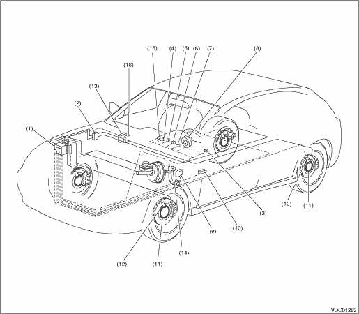
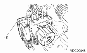
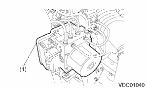
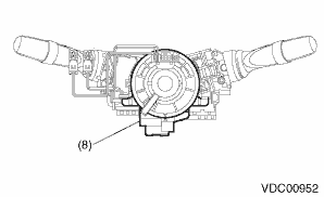
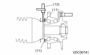
(1) | VDC control module and hydraulic control unit (VDCCM&H/U) | (7) | VDC OFF indicator light | (12) | ABS wheel speed sensor |
(2) | Connector | (8) | Steering angle sensor | (13) | Engine control module (ECM) |
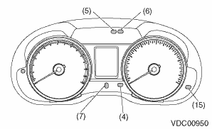
(3) | VDC OFF switch | (9) | Transmission control module (TCM) | (14) | Stop light switch |
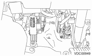
(4) | ABS warning light | (10) | Data link connector | (15) | Hill start assist OFF indicator light / Hill start assist warning light |
(5) | Brake warning light (EBD warning light) | (11) | Magnetic encoder | (16) | Hybrid powertrain control module (HPCM) |
(6) | VDC warning light & VDC indicator light |
• Models without EyeSight
• Models with EyeSight
 Clear memory mode Operation
VEHICLE DYNAMICS CONTROL (VDC) (DIAGNOSTICS) > Clear Memory ModeOPERATION1. On «Start» display, select «Diagnosis».2. On «Vehicle selection» display, input the vehicle information and select ...
 General diagnostic table Inspection
VEHICLE DYNAMICS CONTROL (VDC) (DIAGNOSTICS) > General Diagnostic TableINSPECTIONSymptomsMain probable causeOther probable causePoor brake performanceLong braking/stopping distance• VDCCM& ...
Other materials:
Electrical component location Location
INSTRUMENTATION/DRIVER INFO (DIAGNOSTICS) > Electrical Component LocationLOCATION(1)Combination meter(2)MFD(3)Data link connector ...
Installation
FUEL INJECTION (FUEL SYSTEMS)(H4DO) > Knock SensorINSTALLATION1. Install the knock sensor to the cylinder block.NOTE:The knock sensor should be installed so that the center of the connector is positioned at a 76.5 — 91.5° angle relative to the front of engine.Tightening torque:24 N&m ...
Inspection
EMISSION CONTROL (AUX. EMISSION CONTROL DEVICES)(H4DO) > Purge Control Solenoid ValveINSPECTION1. PURGE CONTROL SOLENOID VALVE1. Check that the purge control solenoid valve has no deformation, cracks or other damages.2. Measure the resistance between the purge control solenoid valve terminals.Ter ...
