Subaru Crosstrek Service Manual: Installation
EXTERIOR/INTERIOR TRIM > Instrument Panel Assembly
INSTALLATION
CAUTION:
• Before handling the airbag system components, refer to “CAUTION” of “General Description” in “AIRBAG SYSTEM”. General Description > CAUTION">
• After installing the panel center assembly, check that the air vent grille of the panel center assembly is inserted correctly into the air vent duct.
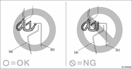
• When installing the cover - instrument panel side (a), make sure that the body side weather strip - flange front does not come inside the panel COMPL - instrument (b).
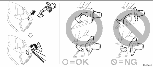
• When reusing the tether clip on the upper part of the trim panel - front pillar UPR, check that there is no damage to the tether clip. If the tether clip is damaged, always replace it with a new tether clip. If the tether clip is damaged, its holding force is reduced and the trim panel - front pillar UPR may come off.
• Do not reuse the tether clip removed from the upper part of the trim panel - front pillar UPR. Always replace with a new part.
• Check the installation status of the tether clips and install the trim panel - front pillar UPR.
1. Attach components until the instrument panel assembly is formed, in the reverse order of removal.
NOTE:
Method of installing insulator
• Adhesive
Use polyurethane adhesive. When assembling the instrument panel assembly, wait until the adhesive has evaporated to prevent filling of the smell in the compartment.
• Double-sided tape
Use commercial double-sided tape. (Use strong double-sided adhesive tape.)
2. Insert the matching pins on the body side (three locations - one in the center and the remaining two on both sides) into the instrument panel assembly and the beam COMPL - steering.
3. Check that the matching pins are inserted securely, and then route the harness.
4. Install the sunload sensor and the grille - front defroster.
5. Secure the instrument panel assembly and the beam COMPL - steering to the vehicle body.
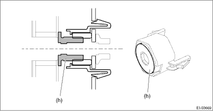
(1) Position the instrument panel assembly and the beam COMPL - steering to the vehicle body and tighten the adjuster - clip space.
Preparation tool:
Hexagon wrench: 8 mm (0.31 in)
NOTE:
Tighten so that there is no gap between the adjuster portion (h) and the body.
Tightening torque:
Adjuster - clip space: 0.8 — 4 N·m (0.08 — 0.41 kgf-m, 0.6 — 2.95 ft-lb)
(2) Temporarily tighten the bolts (a), (b), (c) and (d) of the beam COMPL - steering.
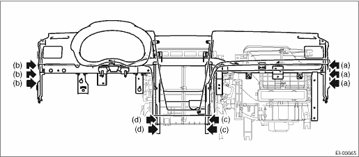
(3) Tighten the beam COMPL - steering in the order from (a) to (d) to the specified torque.
Tightening torque:
Beam COMPL - steering: 25 N·m (2.55 kgf-m, 18.4 ft-lb)
Passenger’s airbag module: 7.5 N·m (0.76 kgf-m, 5.5 ft-lb)
6. Install each part in the reverse order of removal.
Tightening torque:
Column assembly - steering: General Description > COMPONENT">
Knee airbag module: 7.5 N·m (0.76 kgf-m, 5.5 ft-lb)
Console box assembly: 6.5 N·m (0.66 kgf-m, 4.8 ft-lb)

 Removal
EXTERIOR/INTERIOR TRIM > Instrument Panel AssemblyREMOVALCAUTION:• Before handling the airbag system components, refer to “CAUTION” of “General Description” in “ ...
Other materials:
Front differential gear oil (CVT models) and rear differential gear oil
It is not necessary to check the gear oil
level. Check that there are no cracks,
damage or leakage. However, the oil
inspection should be performed according
to the maintenance schedule in the
"Warranty and Maintenance Booklet".
Consult your SUBARU dealer for details.
Recommended grade and ...
Removal
SECURITY AND LOCKS > Keyless BuzzerREMOVAL1. Disconnect the ground cable from battery. NOTE">2. Lift up the vehicle.3. Remove the clips and screws, and turn over the front side of the mud guard - front RH.4. Remove the keyless buzzer.(1) Disconnect the connector.(2) Remove the clip and d ...
Tire size
Your vehicle comes equipped with
P-Metric tire size. It is important to
understand the sizing system in
selecting the proper tire for your
vehicles. Here is a brief review of
the tire sizing system with a breakdown
of its individual elements.
P Metric
With the P-Metric system, Section
Width ...
