Subaru Crosstrek Service Manual: Removal
EXTERIOR/INTERIOR TRIM > Instrument Panel Assembly
REMOVAL
CAUTION:
• Before handling the airbag system components, refer to “CAUTION” of “General Description” in “AIRBAG SYSTEM”. General Description > CAUTION">
• Be careful not to damage the airbag system harness when servicing the instrument panel. Damage may cause the system to malfunction.
NOTE:
Remove the instrument panel assembly and the beam COMPL - steering as a unit.
1. Disconnect the ground cable from battery and wait for at least 60 seconds before starting work. NOTE">
NOTE:
On CVT models, shift the select lever into “N” before disconnecting the battery ground cable.
2. Remove the console box assembly, the cover - shift lever and the panel center LWR on the RH and LH sides. Console Box > REMOVAL">
3. Remove the cover - instrument panel side and the cover assembly - instrument panel LWR driver. Instrument Panel Lower Cover > REMOVAL">
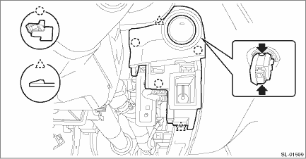
4. Remove the cover switch - starter. (Models without the keyless access with push button start)
(1) Release the claws and remove the cover switch - starter.
(2) Disconnect the connector and aspirator hose.

5. Remove the panel - switch. (Model with keyless access with push button start)
(1) Release the claw of the switch - push button start, and disconnect the connector.
(2) Release the claws, and then remove the panel - switch.
(3) Disconnect the connector and aspirator hose.
6. Remove the knee airbag module. Knee Airbag Module > REMOVAL">
7. Release the clips and claws, then detach the left and right grille speaker side.
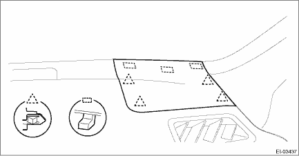
NOTE:
Remove the grille speaker side by using a plastic remover.
8. Remove the trim panel - front pillar UPR on the left and right sides. Upper Inner Trim > REMOVAL">
9. Remove the glove box assembly. Glove Box > REMOVAL">
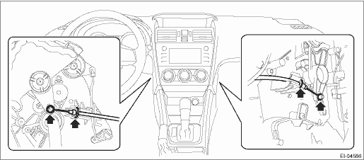
10. On manual A/C models, disconnect the control cables from both sides of the heater & cooling unit.
11. Remove the center grille assembly. Air Vent Grille > REMOVAL">
12. Remove the audio assembly or navigation assembly. Audio > REMOVAL">
13. Remove the multi-function display assembly. Multi-function Display (MFD) > REMOVAL">
14. Remove the combination meter assembly. Combination Meter > REMOVAL">
15. Disconnect the passenger’s airbag module connector. Airbag Connector > PROCEDURE">
16. Remove the column assembly - steering. Steering Column > REMOVAL">
17. Remove the cover side sill - front INN and cover side sill - front on the RH and LH side. Lower Inner Trim > REMOVAL">
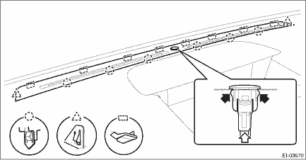
18. Remove the body side weather strip - flange front.
19. Remove the instrument panel assembly and the beam COMPL - steering as a unit.
CAUTION:
The instrument panel assembly and the beam COMPL - steering are heavy. Always work in a team of two persons when removing them from the vehicle, so as not to damage the vehicle interior.
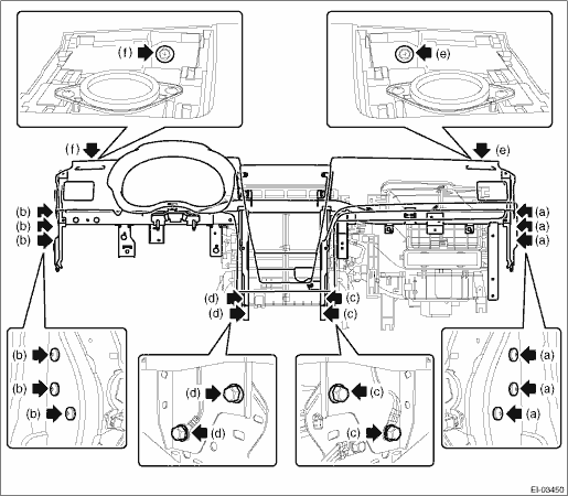
(1) Remove the fuse box and relay box.
(2) Disconnect all harness clamps and connectors of the instrument panel harness.
(3) Remove the TORX® bolt. (a), (b)
Preparation tool:
TORX® T40
(4) Remove the bolts at the floor center. (c), (d)
(5) Remove the bolt. (e), (f)
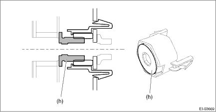
(6) Loosen the adjuster portion (h) of the adjuster - clip space. (Only LH side of the beam COMPL - steering)
Preparation tool:
Hexagon wrench: 8 mm (0.31 in)
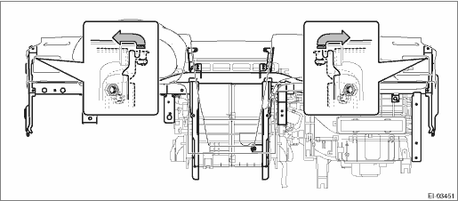
(7) Slightly lift the instrument panel assembly together with the beam COMPL - steering to detach the left and right pins. Then pull it toward you to remove the assembly.
CAUTION:
• Check that all harness clamps and connectors are detached.
• The instrument panel assembly and the beam COMPL - steering are heavy. Always work in a team of two persons when removing them from the vehicle, so as not to damage the vehicle interior.
20. Remove the grille front defroster.
(1) Disconnect the sunload sensor.
(2) Release the claws and remove the grille front defroster.
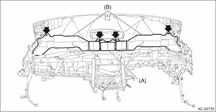
21. Remove the screws and remove the front (A) and side vent duct (B) LH, RH.
22. Separate the panel COMPL - instrument and the beam COMPL - steering.
(1) Remove the clamps and bolts of the passenger’s airbag module harness.
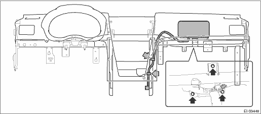
(2) Remove the left and right speakers.
NOTE:
Detach the harness clamp together.
(3) Disconnect the front accessory socket connector.
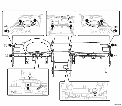
(4) Remove the nut (a) and screws (b), (c), (d), (e), (f), (g) and (h).
(5) While being careful with the harness, separate the panel COMPL - instrument and the beam COMPL - steering.
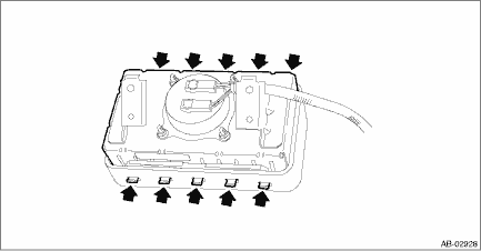
23. Remove the claws, and remove the passenger’s airbag module.
 Installation
EXTERIOR/INTERIOR TRIM > Instrument Panel AssemblyINSTALLATIONCAUTION:• Before handling the airbag system components, refer to “CAUTION” of “General Description” in &l ...

Other materials:
Adjustment
HVAC SYSTEM (HEATER, VENTILATOR AND A/C) > Compressor OilADJUSTMENT• If a component has been replaced, add an appropriate amount of compressor oil (same as the amount of remaining oil in removed component).• When replacing the compressor assembly, the new compressor assembly will alre ...
Installation
ENTERTAINMENT > GPS AntennaINSTALLATIONCAUTION:• After installing the center grille assembly, check that the air vent grille of the center grille assembly is inserted correctly into the air vent duct.• Before handling the airbag system components, always refer to “CAUTION” ...
Clear memory mode Operation
AIRBAG SYSTEM (DIAGNOSTICS) > Clear Memory ModeOPERATION1. On «Start» display, select «Diagnosis».2. On «Vehicle selection» display, input the target vehicle information and select «Confirmed».3. On «Main Menu» display, select «Each System».4. On «Select System» display, select «Ai ...
