Subaru Crosstrek Service Manual: Dtc p2102 throttle actuator "a" control motor circuit low
ENGINE (DIAGNOSTICS)(H4DO) > Diagnostic Procedure with Diagnostic Trouble Code (DTC)
DTC P2102 THROTTLE ACTUATOR "A" CONTROL MOTOR CIRCUIT LOW
DTC DETECTING CONDITION:
Immediately at fault recognition
TROUBLE SYMPTOM:
• Improper idling
• Poor driving performance
• Engine stall
CAUTION:
After servicing or replacing faulty parts, perform Clear Memory Mode Clear Memory Mode > OPERATION"> , and Inspection Mode Inspection Mode > PROCEDURE">.
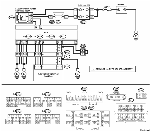
WIRING DIAGRAM:
Engine electrical system Engine Electrical System">
| STEP | CHECK | YES | NO |
1.CHECK ELECTRONIC THROTTLE CONTROL RELAY.
1) Turn the ignition switch to OFF.
2) Remove the electronic throttle control relay.
3) Connect the battery to terminals No. 16 and No. 17 of electronic throttle control relay.
4) Measure the resistance between electronic throttle control relay terminals.
Terminals
No. 14 — No. 15:
Is the resistance less than 1 ??
Diagnostic Procedure with Diagnostic Trouble Code (DTC) > DTC P2102 THROTTLE ACTUATOR "A" CONTROL MOTOR CIRCUIT LOW">Go to Step 2.
Replace the electronic throttle control relay. Electronic Throttle Control Relay">
2.CHECK POWER SUPPLY OF ELECTRONIC THROTTLE CONTROL RELAY.
Measure the voltage between electronic throttle control relay connector and chassis ground.
Connector & terminal
(B225) No. 15 (+) — Chassis ground (−):
Is the voltage 10 V or more?
Diagnostic Procedure with Diagnostic Trouble Code (DTC) > DTC P2102 THROTTLE ACTUATOR "A" CONTROL MOTOR CIRCUIT LOW">Go to Step 3.
Repair the open or short to ground in the power supply circuit.
3.CHECK HARNESS BETWEEN ECM AND ELECTRONIC THROTTLE CONTROL RELAY CONNECTOR.
1) Disconnect the connector from ECM.
2) Turn the ignition switch to ON.
3) Measure the voltage between electronic throttle control relay connector and chassis ground.
Connector & terminal
(B225) No. 17 (+) — Chassis ground (−):
Is the voltage 10 V or more?
Repair the short circuit to power in the harness between ECM connector and electronic throttle control relay connector.
Diagnostic Procedure with Diagnostic Trouble Code (DTC) > DTC P2102 THROTTLE ACTUATOR "A" CONTROL MOTOR CIRCUIT LOW">Go to Step 4.
4.CHECK HARNESS BETWEEN ECM AND ELECTRONIC THROTTLE CONTROL RELAY CONNECTOR.
1) Turn the ignition switch to OFF.
2) Measure the resistance between electronic throttle control relay connector and chassis ground.
Connector & terminal
(B225) No. 14 — Chassis ground:
(B225) No. 17 — Chassis ground:
Is the resistance 1 M? or more?
Diagnostic Procedure with Diagnostic Trouble Code (DTC) > DTC P2102 THROTTLE ACTUATOR "A" CONTROL MOTOR CIRCUIT LOW">Go to Step 5.
Repair the short circuit to ground in harness between ECM connector and electronic throttle control relay connector.
5.CHECK HARNESS BETWEEN ECM AND ELECTRONIC THROTTLE CONTROL RELAY CONNECTOR.
Measure the resistance between ECM connector and electronic throttle control relay connector.
Connector & terminal
(B135) No. 17 — (B225) No. 17:
(B135) No. 7 — (B225) No. 14:
Is the resistance less than 1 ??
Repair the poor contact of ECM connector.
Repair the open circuit in harness between ECM connector and electronic throttle control relay connector.
1. OUTLINE OF DIAGNOSIS
Judge as NG when the electronic throttle control power is not supplied even when ECM sets the electric control throttle relay to ON.
2. COMPONENT DESCRIPTION
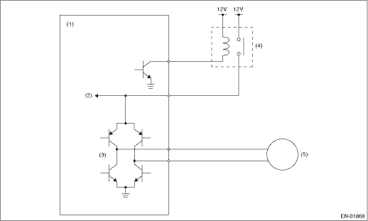
(1) | Engine control module (ECM) | (3) | Drive circuit | (5) | Motor |
(2) | Voltage detection circuit | (4) | Electronic throttle control relay |
3. EXECUTION CONDITION
Secondary Parameters | Execution condition |
Battery voltage | ≥ 11 V |
Electronic throttle control relay output | ON |
4. GENERAL DRIVING CYCLE
Always perform the diagnosis continuously.
5. DIAGNOSTIC METHOD
If the duration of time while the following conditions are met is longer than the time indicated, judge as NG.
Malfunction Criteria | Threshold Value |
Motor power voltage | ≤ 5 V |
Time Needed for Diagnosis: 352 ms
Malfunction Indicator Light Illumination: Illuminates as soon as a malfunction occurs.
 Dtc p2101 throttle actuator "a" control motor circuit range/performance
ENGINE (DIAGNOSTICS)(H4DO) > Diagnostic Procedure with Diagnostic Trouble Code (DTC)DTC P2101 THROTTLE ACTUATOR "A" CONTROL MOTOR CIRCUIT RANGE/PERFORMANCEDTC detecting condition:Immediat ...
 Dtc p2103 throttle actuator "a" control motor circuit high
ENGINE (DIAGNOSTICS)(H4DO) > Diagnostic Procedure with Diagnostic Trouble Code (DTC)DTC P2103 THROTTLE ACTUATOR "A" CONTROL MOTOR CIRCUIT HIGHDTC DETECTING CONDITION:Immediately at fault ...
Other materials:
12
CRUISE CONTROL SYSTEM (DIAGNOSTICS) > Diagnostic Procedure with Cancel Code12Detected when brake pedal is depressed or malfunction related to stop light & brake switch occurs.TROUBLE SYMPTOM:• Cruise control cannot be set.• Cruise control cannot be released.WIRING DIAGRAM:Cruise c ...
Diagnostic procedure for subaru select monitor communication Communication for initializing impossible
HVAC SYSTEM (AUTO A/C) (DIAGNOSTICS) > Diagnostic Procedure for Subaru Select Monitor CommunicationCOMMUNICATION FOR INITIALIZING IMPOSSIBLEDiagnosis:Defective CAN communication circuitTrouble symptom:• LAN system is abnormal.• Communication failure between Subaru Select Monitor and A ...
Key lock-in prevention function
The Subaru Ascent is equipped with a key lock-in prevention system designed to
prevent accidental locking of the keys inside the vehicle.
Under the following conditions, the Subaru Ascent doors will not lock when the
door lock switch is pressed while a front door remains open:
The key is st ...
