Subaru Crosstrek Service Manual: Diagnostic procedure for subaru select monitor communication Communication for initializing impossible
HVAC SYSTEM (AUTO A/C) (DIAGNOSTICS) > Diagnostic Procedure for Subaru Select Monitor Communication
COMMUNICATION FOR INITIALIZING IMPOSSIBLE
Diagnosis:
Defective CAN communication circuit
Trouble symptom:
• LAN system is abnormal.
• Communication failure between Subaru Select Monitor and A/C control panel
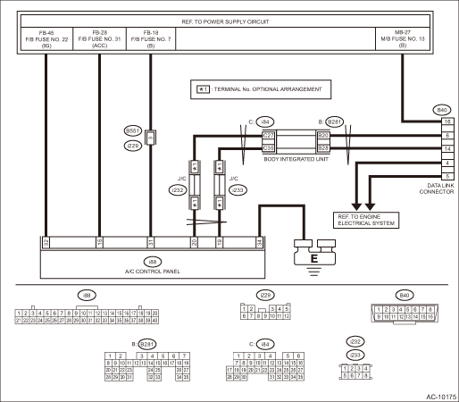
Wiring diagram:
Air conditioning system Air Conditioning System > WIRING DIAGRAM">
| STEP | CHECK | YES | NO |
1.CHECK POWER SUPPLY CIRCUIT.
Connect DST-i to data link connector.
Does DST-i turn ON?
Diagnostic Procedure for Subaru Select Monitor Communication > COMMUNICATION FOR INITIALIZING IMPOSSIBLE">Go to Step 4.
Diagnostic Procedure for Subaru Select Monitor Communication > COMMUNICATION FOR INITIALIZING IMPOSSIBLE">Go to Step 2.
2.CHECK POWER SUPPLY CIRCUIT.
Measure the voltage between data link connector and chassis ground.
Connector & terminal
(B40) No. 16 (+) — Chassis ground (−):
Is the voltage 10 V or more?
Diagnostic Procedure for Subaru Select Monitor Communication > COMMUNICATION FOR INITIALIZING IMPOSSIBLE">Go to Step 3.
Repair the power supply circuit.
NOTE:
In this case, repair the following item:
• Open or ground short circuit of harness between battery and data link connector
• Blown out of fuse (M/B No. 12)
3.CHECK HARNESS BETWEEN DATA LINK CONNECTOR AND CHASSIS GROUND (OPEN).
1) Turn the ignition switch to OFF.
2) Measure the resistance of harness between data link connector and chassis ground.
Connector & terminal
(B40) No. 4 — Chassis ground:
(B40) No. 5 — Chassis ground:
Is the resistance less than 5 ??
Repair the poor contact of data link connector.
Repair the harness and connector.
4.CHECK SUBARU SELECT MONITOR.
1) Connect the Subaru Select Monitor to a normal vehicle.
2) Start the engine and perform communication between the Subaru Select Monitor and vehicle.
Is communication possible?
Diagnostic Procedure for Subaru Select Monitor Communication > COMMUNICATION FOR INITIALIZING IMPOSSIBLE">Go to Step 5.
Use another Subaru Select Monitor because the CAN communication circuit of the Subaru Select Monitor is faulty.
5.CHECK LAN SYSTEM.
Check the LAN system. Basic Diagnostic Procedure > PROCEDURE">
Is LAN system normal?
Diagnostic Procedure for Subaru Select Monitor Communication > COMMUNICATION FOR INITIALIZING IMPOSSIBLE">Go to Step 6.
Repair it according to the diagnosis for LAN system.
6.CHECK CONNECTOR.
Check for poor contact of power supply circuit connector.
Is there poor contact of connector?
Repair the connector.
Diagnostic Procedure for Subaru Select Monitor Communication > COMMUNICATION FOR INITIALIZING IMPOSSIBLE">Go to Step 7.
7.CHECK FUSE.
1) Turn the ignition switch to OFF.
2) Remove a fuse from the fuse box.
3) Check the fuse.
Is the fuse blown out?
Replace the fuse.
Diagnostic Procedure for Subaru Select Monitor Communication > COMMUNICATION FOR INITIALIZING IMPOSSIBLE">Go to Step 8.
8.CHECK A/C CONTROL PANEL POWER CIRCUIT.
1) Disconnect the A/C control panel connector.
2) Measure the voltage between A/C control panel connector terminal and chassis ground after turning the ignition switch to ON.
Connector & terminal
(i88) No. 15 (+) — Chassis ground (−):
(i88) No. 31 (+) — Chassis ground (−):
(i88) No. 32 (+) — Chassis ground (−):
Is the voltage 10 V or more?
Diagnostic Procedure for Subaru Select Monitor Communication > COMMUNICATION FOR INITIALIZING IMPOSSIBLE">Go to Step 9.
Check for open or short circuit in the harness between A/C control panel and fuse.
9.CHECK A/C CONTROL PANEL GROUND CIRCUIT (OPEN).
Measure the resistance of harness between A/C control panel and chassis ground.
Connector & terminal
(i88) No. 34 — Chassis ground:
Is the resistance less than 5 ??
Check the connection between the data link connector and Subaru Select Monitor.
Repair the harness for ground line.
 Clear memory mode Operation
HVAC SYSTEM (AUTO A/C) (DIAGNOSTICS) > Clear Memory ModeOPERATION1. On «Start» display, select «Diagnosis».2. On «Vehicle selection» display, input the target vehicle information and select  ...
 Electrical component location Location
HVAC SYSTEM (AUTO A/C) (DIAGNOSTICS) > Electrical Component LocationLOCATION1. OUTSIDE VEHICLE(1)A/C compressor(3)Pressure switch(4)Ambient sensor(2)A/C relay 2. COMPARTMENT(1)Air mix door actua ...
Other materials:
Snow tires
WARNING
When replacing or installing winter
tire(s), all four tires must be
the same for following items.
(a) Size
(b) Circumference
(c) Speed symbol
(d) Load index
(e) Construction
(f) Manufacturer
(g) Brand (tread pattern)
(h) Degrees of wear
For the items (a) to (d), you must
obey th ...
Cargo tie-down hooks
The Subaru Ascent cargo area includes multiple tie-down hooks that can be used
to secure items with straps, nets, or ropes, helping prevent movement during transit.
To use them, fold the hooks out from their recessed positions.
CAUTION
The tie-down hooks in the Subaru Ascent are intended fo ...
Removal
HVAC SYSTEM (HEATER, VENTILATOR AND A/C) > Evaporator SensorREMOVALCAUTION:Before handling the airbag system components, refer to “CAUTION” of “General Description” in “AIRBAG SYSTEM”. General Description > CAUTION">1. Using the refrigerant recovery ...
