Subaru Crosstrek Service Manual: Inspection
LIGHTING SYSTEM > Spot Map Light
INSPECTION
1. SPOT MAP LIGHT BULB
1. Visually check the bulb for blow out.
2. Check the bulb specification. General Description > SPECIFICATION">
3. Replace the bulb if it is found defective.
2. SPOT MAP LIGHT SWITCH
1. Check the resistance between switch terminals.
Preparation tool:
Circuit tester
• Models without EyeSight
– Model without sunroof
Terminal No. | Inspection conditions | Standard | Connection diagram |
1 — 2 | Switch OFF | 1 M? or more |
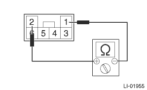
Switch ON
Approx. 18 ?
– Model with sunroof
Terminal No. | Inspection conditions | Standard | Connection diagram |
1 — 4 | Switch OFF | 1 M? or more |
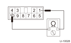
Switch ON
Approx. 18 ?
• Models with EyeSight
Terminal No. | Inspection conditions | Standard | Connection diagram |
11 — 12 | Switch OFF | 1 M? or more |
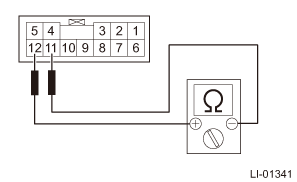
Switch ON
Approx. 18 ?
2. Replace the light assembly - map if the inspection result is not within the standard value.
 Spot map light
...
 Removal
LIGHTING SYSTEM > Spot Map LightREMOVAL1. MODELS WITHOUT EyeSight1. Disconnect the ground cable from battery. NOTE">2. Remove the light assembly - map.CAUTION:When using a flat tip screwdr ...
Other materials:
Inspection
CRUISE CONTROL SYSTEM > Cruise Control Command SwitchINSPECTION1. Measure the resistance between connector terminals.Preparation tool:Circuit testerTerminal No.Inspection conditionsStandard3 — 9CANCELSET/−RES/+All OFFApprox. 4,020 ?CANCELONLess than 1 ?SET/−ONApprox. 250 ?RES/+ONApp ...
Adjustment
BRAKE > Stop Light SwitchADJUSTMENT1. BULB TYPECAUTION:• Turn the stop light switch clockwise when installing so that it can return backward by approximately 1 mm (0.04 in) and clearance is automatically adjusted.• If it is hard to turn the switch, reduce the switch pushing force and ...
Touch screen operation
This system is operated mainly by the
keys on the screen.
When a screen key is touched, a beep
sounds. You can set the beep sound.
Refer to "Unit settings"
NOTE
If the system does not respond to
touching a screen key, move your
finger away from the screen and touch
it again.
Gra ...
