Subaru Crosstrek Service Manual: Inspection
CRUISE CONTROL SYSTEM > Cruise Control Command Switch
INSPECTION
1. Measure the resistance between connector terminals.
Preparation tool:
Circuit tester
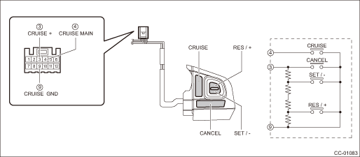
Terminal No. | Inspection conditions | Standard | |
3 — 9 | CANCEL SET/− RES/+ | All OFF | Approx. 4,020 ? |
CANCEL | ON | Less than 1 ? | |
SET/− | ON | Approx. 250 ? | |
RES/+ | ON | Approx. 1,470 ? | |
4 — 9 | CRUISE (MAIN) | OFF | 1 M? or more |
ON | Less than 1 ? | ||
2. Apply battery voltage between the connector terminals to check lighting condition of illumination inside the switch.
Terminal No. | Inspection conditions | Specification |
10 (+) — 11 (−) | Apply battery voltage. | Light ON |
3. Replace the cruise control command switch assembly if it is found defective.

 Removal
CRUISE CONTROL SYSTEM > Cruise Control Command SwitchREMOVALCAUTION:Before handling the airbag system components, refer to “CAUTION” of “General Description” in “AIRBA ...
Other materials:
Windshield wipers
Mist (for a single wipe)
Off
Intermitten
Low speed
High speed
To turn the wipers on, push the wiper
control lever down.
To turn the wipers off, return the lever to
the " " position.
For a single wipe of the wipers, push the
lever up. The wipers operate until you
release the lever. ...
Tire pressure warning light is 25 times blinking and turn on
TIRE PRESSURE MONITORING SYSTEM (DIAGNOSTICS) > Tire Pressure Warning Light / Trouble Indicator Light Illumination PatternTIRE PRESSURE WARNING LIGHT IS 25 TIMES BLINKING AND TURN ONDetecting condition:• Defective TPMS & keyless entry CM or TPMS CM• Defective harness• Transm ...
Inspection
CONTINUOUSLY VARIABLE TRANSMISSION(TR580) > Inhibitor SwitchINSPECTIONWhen the driving condition or starter motor operation is improper, first check the shift linkage for improper operation. If the shift linkage is functioning properly, check the inhibitor switch.1. Remove the clip (A) from the a ...
