Subaru Crosstrek Service Manual: Dtc b1409 scu communication
IMMOBILIZER (DIAGNOSTICS) > Diagnostic Procedure with Diagnostic Trouble Code (DTC)
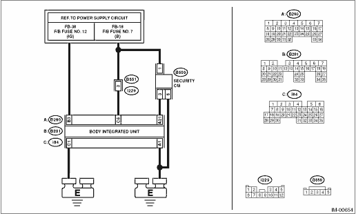
DTC B1409 SCU COMMUNICATION
DTC detecting condition:
Communication failure between body integrated unit and security control module
CAUTION:
When the body integrated unit is replaced, registration of the immobilizer system is required. For details, refer to the “REGISTRATION MANUAL FOR IMMOBILIZER” provided as a separate volume.
Wiring diagram:
Immobilizer system Immobilizer System > WIRING DIAGRAM">
| STEP | CHECK | YES | NO |
1.CHECK GROUNDING POINT.
Check the ground point of chassis ground.
Are there any loose connections, any foreign objects caught in the ground lines or contact surface, or any fluid stains?
Remove the foreign matters, and tighten to the specified torque. Then start the engine, and check that the fault was removed. Check DTC Read Diagnostic Trouble Code (DTC)">, and when DTC B1572 is still displayed, Diagnostic Procedure with Diagnostic Trouble Code (DTC) > DTC B1409 SCU COMMUNICATION">Go to Step 2.
Diagnostic Procedure with Diagnostic Trouble Code (DTC) > DTC B1409 SCU COMMUNICATION">Go to Step 2.
2.CHECK BODY INTEGRATED UNIT POWER SUPPLY CIRCUIT.
1) Turn the ignition switch to OFF.
2) Disconnect the connector from body integrated unit.
3) Measure the voltage between the body integrated unit connector terminal and chassis ground.
Connector & terminal
(i84) No. 6 (+) — Chassis ground (−):
Is the voltage 10 V or more?
Diagnostic Procedure with Diagnostic Trouble Code (DTC) > DTC B1409 SCU COMMUNICATION">Go to Step 3.
Check the harness for open or short circuit between body integrated unit and fuse.
3.CHECK BODY INTEGRATED UNIT POWER SUPPLY CIRCUIT.
1) Turn the ignition switch to ON.
2) Measure the voltage between the body integrated unit connector terminal and chassis ground.
Connector & terminal
(B281) No. 3 (+) — Chassis ground (−):
Is the voltage 10 V or more?
Diagnostic Procedure with Diagnostic Trouble Code (DTC) > DTC B1409 SCU COMMUNICATION">Go to Step 4.
Check the harness for open or short circuit between the body integrated unit and ignition switch.
4.CHECK BODY INTEGRATED UNIT GROUND CIRCUIT (OPEN CIRCUIT).
1) Turn the ignition switch to OFF.
2) Measure the resistance between the body integrated unit connector terminal and chassis ground.
Connector & terminal
(B280) No. 1 — Chassis ground:
(i84) No. 1 — Chassis ground:
Is the resistance less than 10 ??
Diagnostic Procedure with Diagnostic Trouble Code (DTC) > DTC B1409 SCU COMMUNICATION">Go to Step 5.
Repair the open circuit of the body integrated unit ground circuit.
5.CHECK SECURITY CONTROL MODULE POWER SUPPLY CIRCUIT.
1) Disconnect the connector from the security control module.
2) Measure the voltage between security control module connector terminal and chassis ground.
Connector & terminal
(B559) No. 1 (+) — Chassis ground (−):
Is the voltage 10 V or more?
Diagnostic Procedure with Diagnostic Trouble Code (DTC) > DTC B1409 SCU COMMUNICATION">Go to Step 6.
Check for an open or short circuit in the harness between security control module and fuse.
6.CHECK SECURITY CONTROL MODULE GROUND CIRCUIT (OPEN).
Measure the resistance between security control module connector terminal and chassis ground.
Connector & terminal
(B559) No. 5 — Chassis ground:
Is the resistance less than 10 ??
Diagnostic Procedure with Diagnostic Trouble Code (DTC) > DTC B1409 SCU COMMUNICATION">Go to Step 7.
Repair the open circuit of the security control module ground circuit.
7.CHECK HARNESS (OPEN CIRCUIT) BETWEEN BODY INTEGRATED UNIT AND SECURITY CONTROL MODULE.
Measure the resistance between the body integrated unit connector terminal and security control module connector terminal.
Connector & terminal
(B280) No. 21 — (B559) No. 3:
Is the resistance less than 10 ??
Diagnostic Procedure with Diagnostic Trouble Code (DTC) > DTC B1409 SCU COMMUNICATION">Go to Step 8.
Repair the harness between body integrated unit and security control module.
8.CHECK COMMUNICATION LINE HARNESS (SHORT CIRCUIT TO POWER SUPPLY).
1) Turn the ignition switch to ON.
2) Measure the voltage between security control module connector terminal and chassis ground.
Connector & terminal
(B559) No. 3 (+) — Chassis ground (−):
Is the voltage 6 V or more?
Repair the harness between body integrated unit and security control module.
Diagnostic Procedure with Diagnostic Trouble Code (DTC) > DTC B1409 SCU COMMUNICATION">Go to Step 9.
9.CHECK COMMUNICATION CIRCUIT HARNESS (SHORT CIRCUIT TO GROUND).
1) Turn the ignition switch to OFF.
2) Measure the resistance between security control module connector terminal and chassis ground.
Connector & terminal
(B559) No. 3 — Chassis ground:
Is the resistance less than 10 ??
Repair the harness between body integrated unit and ECM.
Diagnostic Procedure with Diagnostic Trouble Code (DTC) > DTC B1409 SCU COMMUNICATION">Go to Step 10.
10.CHECK SECURITY CONTROL MODULE.
1) Replace the security control module. (Do not perform security control module registration.)
2) Turn the ignition switch to ON.
3) Perform the Clear Memory Mode. Clear Memory Mode">
4) Read the DTC of the body integrated unit. Read Diagnostic Trouble Code (DTC)">
Is DTC B1409 detected?
Replace the body integrated unit. Body Integrated Unit">
Security control module was defective. Perform security control module registration. Refer to the “REGISTRATION MANUAL FOR IMMOBILIZER” provided as a separate volume.
 Dtc b1408 meter non-volatile memory
IMMOBILIZER (DIAGNOSTICS) > Diagnostic Procedure with Diagnostic Trouble Code (DTC)DTC B1408 METER NON-VOLATILE MEMORYDTC DETECTING CONDITION:Defective combination meterCAUTION:When the combination ...
 Dtc b1410 transponder communication
IMMOBILIZER (DIAGNOSTICS) > Diagnostic Procedure with Diagnostic Trouble Code (DTC)DTC B1410 TRANSPONDER COMMUNICATIONNOTE:Refer to DTC B1574 for diagnostic procedure. Diagnostic Procedure with Di ...
Other materials:
Selecting a channel from the list
1. The categories list is displayed via
either of the following procedures.
When you touch the
tab in the
SiriusXM main screen (if the list that
was displayed the last time is Categories).
When you select the tab in
each
list screen.
2. Each channel list is displayed whe ...
Inspection
SECURITY AND LOCKS > Front Outer HandleINSPECTIONCheck if the outer handle operates normally.• If the lever is faulty, replace the handle - door outer.• If the rod is deformed, replace the latch & actuator assembly - front.For models with keyless access system with push button sta ...
Dtc p2747 intermediate shaft speed sensor "b" circuit no signal
CONTINUOUSLY VARIABLE TRANSMISSION (DIAGNOSTICS) > Diagnostic Procedure with Diagnostic Trouble Code (DTC)DTC P2747 INTERMEDIATE SHAFT SPEED SENSOR "B" CIRCUIT NO SIGNALDTC detecting condition:Immediately at fault recognitionTrouble symptom:• Standing start problems• Shock o ...
