Subaru Crosstrek Service Manual: Adjustment
BRAKE > Stop Light Switch
ADJUSTMENT
1. BULB TYPE
CAUTION:
• Turn the stop light switch clockwise when installing so that it can return backward by approximately 1 mm (0.04 in) and clearance is automatically adjusted.
• If it is hard to turn the switch, reduce the switch pushing force and turn it again.
• After adjustment, if the pedal stroke is less than 3 mm (0.12 in), it may lead to an incorrect light illumination by vibrations etc.
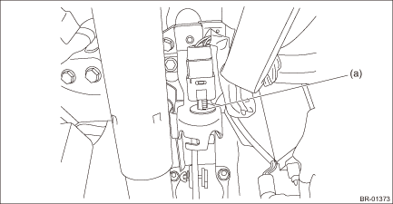
1. Mark the threaded portion of the stop light switch (a).
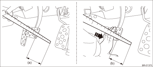
2. Measure the brake pedal stroke which turns on the stop light switch.
(1) Measure the distance (a) from the floor mat to the end of brake pedal pad.
(2) Hold the pedal to a position that the stop light illuminates, and measure the distance (b) from the floor mat to the end of brake pedal pad.
(3) Calculate the difference (stroke value) between the values (a) and (b) measured as above.
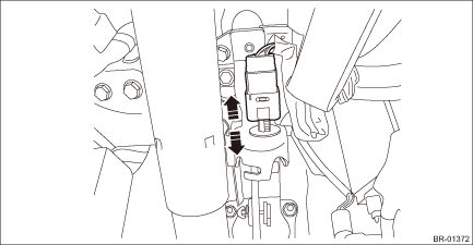
3. Adjust so that the calculated difference of stroke value fit within the specified value, and install the stop light switch.
Specification:
3 mm (0.12 in) or more, less than 8 mm (0.31 in)
NOTE:
Pedal stroke volume per a pitch becomes approx. 5 mm (0.2 in).
4. After adjustment, make sure that the stop light switch illuminates normally.
2. LED TYPE
1. While pulling up the brake pedal (c) toward you, insert the switch - stop light (a) until it reaches the stopper (b).
2. Install the switch - stop light by turning it clockwise.
CAUTION:
Turn the stop light switch clockwise when installing so that it can return backward by approximately 1 mm (0.04 in) and clearance is automatically adjusted.
Insert until it contacts the stopper, and make sure that clearance (A) of the end of stop light switch and the stopper is 1 mm — 2 mm (0.04 in — 0.08 in).
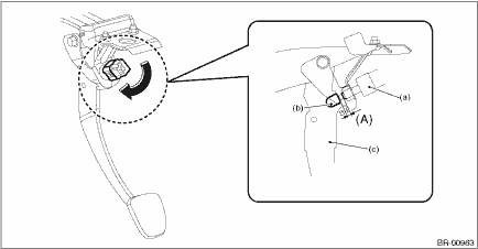
(a) | Stop light switch | (b) | Stopper | (c) | Brake pedal |
3. After adjustment, make sure that the stop light switch illuminates normally.

 Removal
BRAKE > Stop Light SwitchREMOVALCAUTION:Before handling the airbag system components, always refer to “CAUTION” of “General Description” in “AIRBAG SYSTEM”. Gen ...
Other materials:
Immobilizer system Wiring diagram
WIRING SYSTEM > Immobilizer SystemWIRING DIAGRAM1. WITHOUT PUSH BUTTON START2. WITH PUSH BUTTON START ...
Removal
LIGHTING SYSTEM > Rear Height SensorREMOVALCAUTION:Always remove the sensor assembly - headlight beam leveler before removing any parts related to the suspension.1. Disconnect the ground cable from battery. NOTE">2. Lift up the vehicle, and remove the left rear wheel.3. Remove the sensor ...
Security indicator light
The security indicator light in the Subaru Ascent provides important information
regarding the status of both the alarm system and the immobilizer system, helping
to ensure vehicle security at all times.
Alarm system
This indicator blinks to inform the driver that the alarm system of the Subar ...
