Subaru Crosstrek Service Manual: Dtc p0122 throttle/pedal position sensor/switch "a" circuit low
ENGINE (DIAGNOSTICS)(H4DO) > Diagnostic Procedure with Diagnostic Trouble Code (DTC)
DTC P0122 THROTTLE/PEDAL POSITION SENSOR/SWITCH "A" CIRCUIT LOW
DTC detecting condition:
Immediately at fault recognition
Trouble symptom:
• Improper idling
• Engine stall
• Poor driving performance
CAUTION:
After servicing or replacing faulty parts, perform Clear Memory Mode Clear Memory Mode > OPERATION"> , and Inspection Mode Inspection Mode > PROCEDURE">.
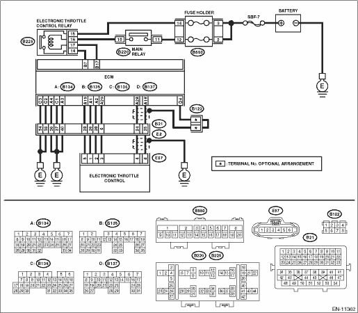
Wiring diagram:
Engine electrical system Engine Electrical System">
| STEP | CHECK | YES | NO |
1.CHECK HARNESS BETWEEN ECM AND ELECTRONIC THROTTLE CONTROL CONNECTOR.
1) Turn the ignition switch to OFF.
2) Disconnect the connector from ECM.
3) Disconnect the connectors from electronic throttle control.
4) Measure the resistance between ECM connector and chassis ground.
Connector & terminal
(B134) No. 19 — Chassis ground:
(B134) No. 18 — Chassis ground:
(B134) No. 18 — (B136) No. 4:
Is the resistance 1 M? or more?
Diagnostic Procedure with Diagnostic Trouble Code (DTC) > DTC P0122 THROTTLE/PEDAL POSITION SENSOR/SWITCH "A" CIRCUIT LOW">Go to Step 2.
Repair the ground short circuit of harness between ECM connector and electronic throttle control connector.
2.CHECK SHORT CIRCUIT INSIDE THE ECM.
1) Connect the connector to ECM.
2) Measure the resistance between electronic throttle control connector and engine ground.
Connector & terminal
(E57) No. 6 — Engine ground:
Is the resistance 1 M? or more?
Replace the electronic throttle control. Throttle Body">
Repair the ground short circuit of harness between ECM connector and electronic throttle control connector. Replace the ECM if defective. Engine Control Module (ECM)">
1. OUTLINE OF DIAGNOSIS
Detect the open or short circuit of throttle position sensor 1.
Judge as NG if out of specification.
2. COMPONENT DESCRIPTION
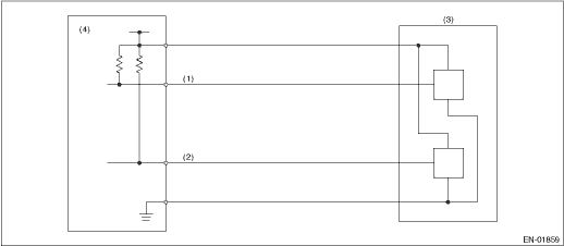
(1) | Throttle position sensor 1 signal | (3) | Throttle position sensor | (4) | Engine control module (ECM) |
(2) | Throttle position sensor 2 signal |
3. EXECUTION CONDITION
Secondary Parameters | Execution condition |
Battery voltage | ≥ 6 V |
4. GENERAL DRIVING CYCLE
Always perform the diagnosis continuously.
5. DIAGNOSTIC METHOD
If the duration of time while the following conditions are met is longer than the time indicated, judge as NG.
Malfunction Criteria | Threshold Value |
Sensor 1 input voltage | ≤ 0.267 V |
Time Needed for Diagnosis: 24 ms
Malfunction Indicator Light Illumination: Illuminates as soon as a malfunction occurs.
 Dtc p0118 engine coolant temperature sensor 1 circuit high
ENGINE (DIAGNOSTICS)(H4DO) > Diagnostic Procedure with Diagnostic Trouble Code (DTC)DTC P0118 ENGINE COOLANT TEMPERATURE SENSOR 1 CIRCUIT HIGHDTC detecting condition:Immediately at fault recognitio ...
 Dtc p0123 throttle/pedal position sensor/switch "a" circuit high
ENGINE (DIAGNOSTICS)(H4DO) > Diagnostic Procedure with Diagnostic Trouble Code (DTC)DTC P0123 THROTTLE/PEDAL POSITION SENSOR/SWITCH "A" CIRCUIT HIGHDTC detecting condition:Immediately at ...
Other materials:
Inspection
EMISSION CONTROL (AUX. EMISSION CONTROL DEVICES)(H4DO) > Purge Control Solenoid ValveINSPECTION1. PURGE CONTROL SOLENOID VALVE1. Check that the purge control solenoid valve has no deformation, cracks or other damages.2. Measure the resistance between the purge control solenoid valve terminals.Ter ...
Electrical component location Location
KEYLESS ACCESS WITH PUSH BUTTON START SYSTEM (DIAGNOSTICS) > Electrical Component LocationLOCATION(1)Keyless access CM(8)Push button ignition switch(15)Rear interior antenna(2)Mechanical key(9)Steering lock CM(16)Rear gate opener button(3)Access key(10)TCM(17)Rear lock button(4)Front outer handle ...
Light control switch
CAUTION
Use of any lights for a long period
of time while the engine is not
running can cause the battery to
discharge.
Before leaving the vehicle, make
sure that the lights are turned off.
If the vehicle is left unattended
for a long time with the lights
illuminated, the batte ...
