Subaru Crosstrek Service Manual: Installation
MANUAL TRANSMISSION AND DIFFERENTIAL(5MT) > Shifter Fork and Rod
INSTALLATION
1. Install the check ball spring and check ball to the reverse fork rod arm, and press in the ST.
| ST 399411700 | ACCENT BALL INSTALLER |
2. Install the reverse fork rod through the hole on the rear of the transmission case. Press out the ST using the reverse fork rod, and fix with outer snap ring.
3. Install the interlock plunger to reverse fork rod arm.
NOTE:
Apply grease to plunger to prevent it from falling.
4. Position the check ball, check ball spring and gasket in the reverse fork rod hole on the left side of transmission case, and tighten the check ball plug.
NOTE:
Use a new gasket.
Tightening torque:
20 N·m (2.0 kgf-m, 14.8 ft-lb)
5. Install the 1st-2nd fork rod to the 1st-2nd shifter fork through the hole on the rear of the transmission case.
NOTE:
• Set the reverse fork rod to neutral.
• Check that the positions of interlock plunger is correct.
6. Align the holes in the 1st-2nd fork rod and the 1st-2nd shifter fork, and drive a new straight pin into these holes using the ST.
| ST 398791700 | REMOVER |
7. Install the interlock plunger (thin) onto the 3rd-4th fork rod.
NOTE:
Apply grease to plunger to prevent it from falling.
8. Install the 3rd-4th fork rod to the 3rd-4th shifter fork and reverse fork rod arm through the hole on the rear of the transmission case.
9. Align the holes in the 3rd-4th fork rod and the 3rd-4th shifter fork, and drive a new straight pin into these holes.
NOTE:
• Set the reverse fork rod and the 1st-2nd fork rod to neutral.
• Check that the positions of interlock plunger is correct.
| ST 398791700 | REMOVER |
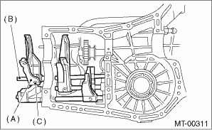
10. Install the 5th shifter fork onto the rear of reverse fork rod. Align the holes in the two parts and drive new straight pin into the specified place.
| ST 398791700 | REMOVER |

(A) | 5th shifter fork |
(B) | Reverse fork rod |
(C) | Straight pin |
11. Position the check balls, check ball springs and gaskets to the 3rd-4th fork rod and 1st-2nd fork rod holes, and install the check ball plugs.
NOTE:
Use a new gasket.
Tightening torque:
20 N·m (2.0 kgf-m, 14.8 ft-lb)

12. Install the front differential assembly. Front Differential Assembly > INSTALLATION">
13. Install the main shaft assembly. Main Shaft Assembly > INSTALLATION">
14. Install the drive pinion shaft assembly. Drive Pinion Shaft Assembly > INSTALLATION">
15. Install the transmission case. Transmission Case > INSTALLATION">
16. Install the transfer case together with the extension case assembly. Transfer Case and Extension Case Assembly > INSTALLATION">
17. Install the back-up light switch and the neutral position switch. Switches and Harness > INSTALLATION">
18. Install the manual transmission assembly to the vehicle. Manual Transmission Assembly > INSTALLATION">
 Removal
MANUAL TRANSMISSION AND DIFFERENTIAL(5MT) > Shifter Fork and RodREMOVAL1. Remove the manual transmission assembly from the vehicle. Manual Transmission Assembly > REMOVAL">2. Remove the ...
Other materials:
Removal
SUNROOF/T-TOP/CONVERTIBLE TOP (SUNROOF) > Sunroof AssemblyREMOVALCAUTION:• Before handling the airbag system components, refer to “CAUTION” of “General Description” in “AIRBAG SYSTEM”. General Description > CAUTION">• When removing the c ...
Dtc c2522 resolver sensor
POWER ASSISTED SYSTEM (POWER STEERING) (DIAGNOSTICS) > Diagnostic Procedure with Diagnostic Trouble Code (DTC)DTC C2522 RESOLVER SENSORTrouble symptom:• The steering wheel operation feels heavy.• STEERING warning light illuminates.Wiring diagram:Electric power steering system Electri ...
Removal
LUBRICATION(H4DO) > Oil PanREMOVAL1. OIL PAN1. Disconnect the ground cable from battery. NOTE">2. Lift up the vehicle.3. Remove the under cover. Front Under Cover > REMOVAL">4. Drain the engine oil. Engine Oil > REPLACEMENT">5. Remove the front exhaust pipe. Fron ...

